rajib.das
Member level 3
Hello There
I am very new in C coding for MCUs
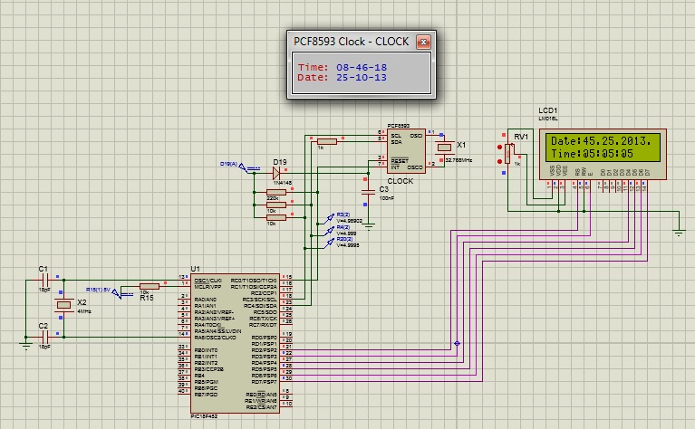
I am using PIC18F452 +PCF8593 + LM016L
Proteus 8.00
Mikro C pro pic
I am keep having LCD out like
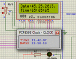
Date:45.25.2003.
Time 555
555
Please I Need serious help
Thanks
- - - Updated - - -
My functions are
I am very new in C coding for MCUs
I am using PIC18F452 +PCF8593 + LM016L
Proteus 8.00
Mikro C pro pic
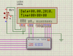
I am keep having LCD out like
Date:45.25.2003.
Time
555Please I Need serious help
Thanks
- - - Updated - - -
My functions are
Code:
// Software I2C connections
sbit Soft_I2C_Scl           at RC3_bit;
sbit Soft_I2C_Sda           at RC4_bit;
// Pin direction
sbit Soft_I2C_Scl_Direction at TRISC3_bit;
sbit Soft_I2C_Sda_Direction at TRISC4_bit;// End Software I2C connections

// -----------Global date/time variables ---------------------------
char seconds;
char minutes;
char hours;
char day;
char month;
char year;

//------------------ Performs project-wide init
void Initiate_Soft_I2C(void) {

     //Soft_I2C_Init();           // Initialize Soft I2C communication
     //TRISC = 0;
     //PORTC = 0x18;
     //TRISC = 0x18;  // ----Making RC0 as Input of 5v--------

     Soft_I2C_Init();           // Initialize Soft I2C communication
}


//--------------------- Reads time and date information from RTC (PCF8583)
void Read_Clock_Time(void) {

     Soft_I2C_Start();               // Issue start signal
     Soft_I2C_Write(0xA0);           // Address PCF8593, see PCF8593 datasheet
     Soft_I2C_Write(2);              // Start from address 2
     Soft_I2C_Start();               // Issue repeated start signal
     Soft_I2C_Write(0xA1);           // Address PCF8593 for reading R/W=1

     seconds = Soft_I2C_Read(1);     // Read seconds byte
     minutes = Soft_I2C_Read(1);     // Read minutes byte
     hours = Soft_I2C_Read(1);       // Read hours byte
     day = Soft_I2C_Read(1);         // Read year/day byte
     month = Soft_I2C_Read(0);       // Read weekday/month byte
     Soft_I2C_Stop();                // Issue stop signal
}

//-------------------- Formats date and time----------------------
void Transform_Time_Variable(void) {
     seconds  =  ((seconds & 0xF0) >> 4)*10 + (seconds & 0x0F);  // Transform seconds
     minutes  =  ((minutes & 0xF0) >> 4)*10 + (minutes & 0x0F);  // Transform months
     hours    =  ((hours & 0xF0)  >> 4)*10  + (hours & 0x0F);    // Transform hours
     year     =   (day & 0xC0) >> 6;                             // Transform year
     day      =  ((day & 0x30) >> 4)*10    + (day & 0x0F);       // Transform day
     month    =  ((month & 0x10)  >> 4)*10 + (month & 0x0F);     // Transform month
}
//------------------------SET TIME and DATE in CLOCK------------------------------
void Set_Clock_Time(void) {

   Delay_ms(1000);
   //Soft_I2C_Init();       // Initialize full master mode
   Soft_I2C_Start();      // Issue start signal
   Soft_I2C_Write(0xA0);  // Address PCF8583, see PCF8583 datasheet
   Soft_I2C_Write(0);     // Start from address 0 (configuration memory location)
   Soft_I2C_Write(0x80);  // Write 0x80 to configuration memory location (pause counter...)
   Soft_I2C_Write(0);     // Write 0 to cents memory location
   Soft_I2C_Write(0);     // Write 0 to seconds memory location
   Soft_I2C_Write(0x30);  // Write 0x30 to minutes memory location
   Soft_I2C_Write(0x12);  // Write 0x12 to hours memory location
   Soft_I2C_Write(0x18);  // Write 0x18 to year/date memory location
   Soft_I2C_Write(0x04);  // Write 0x04 to weekday/month memory location
   Soft_I2C_Stop();       // Issue stop signal

   Soft_I2C_Start();      // Issue start signal
   Soft_I2C_Write(0xA0);  // Address PCF8530
   Soft_I2C_Write(0);     // Start from address 0
   Soft_I2C_Write(0);     // Write 0 to configuration memory location (enable counting)
   Soft_I2C_Stop();       // Issue stop signal
}

//-------------------- Output Format to LCD -------------------------
void Display_Time_Format(void) {
     Lcd_Cmd(_LCD_CLEAR);       // Clear LCD display
     Lcd_Cmd(_LCD_CURSOR_OFF);  // Turn cursor off
     Lcd_Out(1,1,"Date:");      // Prepare and output static text on LCD
     Lcd_Chr(1,8,'.');
     //Lcd_Out(1,8,'.');
     Lcd_Chr(1,11,'.');
     //Lcd_Out(1,11,'.');
     Lcd_Chr(1,16,'.');
     Lcd_Out(2,1,"Time:");
     Lcd_Chr(2,8,':');
     //Lcd_Out(2,8,'.');
     Lcd_Chr(2,11,':');
     //Lcd_Out(2,11,'.');
     Lcd_Out(1,12,"201");       // start from year 2010}
}

//-------------------- Output values to LCD -----------------------------------
void Display_Time(void) {
     Lcd_Chr(1, 6, (day / 10)   + 48);    // Print tens digit of day variable
     Lcd_Chr(1, 7, (day % 10)   + 48);    // Print oness digit of day variable
     Lcd_Chr(1, 9, (month / 10) + 48);
     Lcd_Chr(1,10, (month % 10) + 48);
     Lcd_Chr(1,15,  year        + 48);    // Print year variable  (start from year 2010)

     Lcd_Chr(2, 6, (hours / 10)   + 48);
     Lcd_Chr(2, 7, (hours % 10)   + 48);
     Lcd_Chr(2, 9, (minutes / 10) + 48);
     Lcd_Chr(2,10, (minutes % 10) + 48);
     Lcd_Chr(2,12, (seconds / 10) + 48);
     Lcd_Chr(2,13, (seconds % 10) + 48);
}
Last edited by a moderator: