Continue to Site

Welcome to EDAboard.com

Welcome to our site! EDAboard.com is an international Electronics Discussion Forum focused on EDA software, circuits, schematics, books, theory, papers, asic, pld, 8051, DSP, Network, RF, Analog Design, PCB, Service Manuals... and a whole lot more! To participate you need to register. Registration is free. Click here to register now.

[PIC] LCD 16x2 LCD display doesn't work properly (with pic 16f877A)

Status
Not open for further replies.

A_Nis

Newbie level 5
Joined
Oct 1, 2013
Messages
9
Helped
0
Reputation
0
Reaction score
0
Trophy points
1
Activity points
102
Hi

I have a common issue that most people that its my LCD Display doesn't work when i tried it with PIC16f877A micro-controller

when i input the basic hello world program in to my PIC and the display was like this
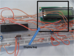
Picture1.png

and sometimes it doesn't display anything at all

i have already checked all the connections several times and it didn't work

After that i decided to check the LCD display without PIC and with the simple connection

pin 1,pin 5,pin 7,pin 8,pin 9,pin10 = GROUND
pin 2 = Vcc(5v)
pin 3 = 10k variable resistor

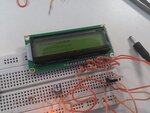
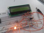
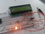
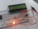
at the first time it displayed like follows and started fading the display
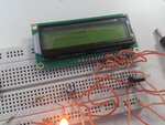
DSC_2979.jpg

DSC_2980.jpg

DSC_2981.jpg

DSC_2982.jpg

DSC_2983.jpg

DSC_2984.jpg

i have read many threads regarding this problem but i couldn't solve it at all
and also i have tried grounding the Pin 3 and doesn't display anything

Hope someone will help me to solve this
THANKS

NOTE
LED which you can see is just to check whether circuit gets the current and it doesn't has any connection with LCD display
 

its 8 MHz does it work or should i have to change it to 4Mhz

but it doesn't work with simple connection(without PIC) fades the display

pin 1,pin 5,pin 7,pin 8,pin 9,pin10 = GROUND
pin 2 = Vcc(5v)
pin 3 = 10k variable resistor
 

This is the circuit and the program
Link ==> https://www.edaboard.com/threads/299985/

but when it doesn't work i tried simple hello world program

Code:
 // LCD module connections
sbit LCD_RS at RB2_bit;
sbit LCD_EN at RB3_bit;
sbit LCD_D4 at RB4_bit;
sbit LCD_D5 at RB5_bit;
sbit LCD_D6 at RB6_bit;
sbit LCD_D7 at RB7_bit;

sbit LCD_RS_Direction at TRISB2_bit;
sbit LCD_EN_Direction at TRISB3_bit;
sbit LCD_D4_Direction at TRISB4_bit;
sbit LCD_D5_Direction at TRISB5_bit;
sbit LCD_D6_Direction at TRISB6_bit;
sbit LCD_D7_Direction at TRISB7_bit;
// End LCD module connections
void main()
{
  Lcd_Init();                        // Initialize LCD
  Lcd_Cmd(_LCD_CLEAR);               // Clear display
  Lcd_Cmd(_LCD_CURSOR_OFF);          // Cursor off
  Lcd_Out(1,1,"Hello World");        // Write text'Hello World' in first row
}
 

while(1) is missing bro?
 
  • Like
Reactions: A_Nis

    A_Nis

    Points: 2
    Helpful Answer Positive Rating

Code C - [expand]
1
2
3
4
5
6
7
8
9
10
11
12
13
14
15
16
17
18
19
20
21
22
23
24
25
26
27
28
// LCD module connections
sbit LCD_RS at RB2_bit;
sbit LCD_EN at RB3_bit;
sbit LCD_D4 at RB4_bit;
sbit LCD_D5 at RB5_bit;
sbit LCD_D6 at RB6_bit;
sbit LCD_D7 at RB7_bit;
 
sbit LCD_RS_Direction at TRISB2_bit;
sbit LCD_EN_Direction at TRISB3_bit;
sbit LCD_D4_Direction at TRISB4_bit;
sbit LCD_D5_Direction at TRISB5_bit;
sbit LCD_D6_Direction at TRISB6_bit;
sbit LCD_D7_Direction at TRISB7_bit;
// End LCD module connections
 
void main()
{
    TRISB = 0x00;
    PORTB = 0x00;
    
    Lcd_Init();                        // Initialize LCD
    Lcd_Cmd(_LCD_CLEAR);               // Clear display
    Lcd_Cmd(_LCD_CURSOR_OFF);          // Cursor off
    Lcd_Out(1,1,"Hello World");        // Write text'Hello World' in first row
 
    while(1);
}

 
  • Like
Reactions: A_Nis

    A_Nis

    Points: 2
    Helpful Answer Positive Rating
while(1) is missing bro?

oh
:shock:

i'll check it after fixing it
Thank you both :)

- - - Updated - - -

i made the change but it still doesn't display "Hello world " it shows like the 3rd image which i have already posted without the middle line(sorry at the moment i don't have resources to take a photo and post it here)
and also display doesn't fade in this time
 

u adjusted variable pot or not?
 

I did and i'm still struggling to fix it :(
 

ok now try to post your circuit diagram complete because code is looking ok as jayanth mentioned and if u change this code then put your latest code .
 

Code:
// LCD module connections
sbit LCD_RS at RB2_bit;
sbit LCD_EN at RB3_bit;
sbit LCD_D4 at RB4_bit;
sbit LCD_D5 at RB5_bit;
sbit LCD_D6 at RB6_bit;
sbit LCD_D7 at RB7_bit;
 
sbit LCD_RS_Direction at TRISB2_bit;
sbit LCD_EN_Direction at TRISB3_bit;
sbit LCD_D4_Direction at TRISB4_bit;
sbit LCD_D5_Direction at TRISB5_bit;
sbit LCD_D6_Direction at TRISB6_bit;
sbit LCD_D7_Direction at TRISB7_bit;
// End LCD module connections
 
void main()
{
    TRISB = 0x00;
    PORTB = 0x00;
    
    Lcd_Init();                        // Initialize LCD
    Lcd_Cmd(_LCD_CLEAR);               // Clear display
    Lcd_Cmd(_LCD_CURSOR_OFF);          // Cursor off
    Lcd_Out(1,1,"Hello World");        // Write text'Hello World' in first row
 
    while(1);
}

circuit diagram ==>https://www.edaboard.com/threads/299985/
 

The images are too big for me to download on my Internet connection but do you realize the LCD is upside down! The connection pads should be at the top.

I'm guessing you have the wiring correct or you would see nothing at all.

Brian.
 

Hi did you tried the LCD clear and cursor off commented out with while 1.... check the pin details and frequency details..
If still problem persists It may the problem of LCD..
 

first u have to remove the connection of LCD pin no. 7,8,9,10 . and in your code disable the Comparators.
 

I think 'delay' function is missing in your code. And if same problem persists, there might be problem with your power supply. like bad grounding ..etc.
 

Even a 8Mhz crystal is to high to run reliably on breadboard try 4Mhz, can you flash a LED? I have never seen a LCD give the type of display your one does, perhaps it is faulty
 

In my experience of making crystal circuits on breadboard, 4Mhz is OK 8Mhz is iffy and 16Mhz and above does not work. Maybe it is dependent on the type of oscillator, drive levels, type of crystal etc.
 

as you go on crystal frequency you have to increase delay for lcd bcoz lcd are much slower and need to give some time till busy.
 

Status
Not open for further replies.

Similar threads

Part and Inventory Search

Welcome to EDABoard.com

Sponsor

Back
Top