Continue to Site

Welcome to EDAboard.com

Welcome to our site! EDAboard.com is an international Electronics Discussion Forum focused on EDA software, circuits, schematics, books, theory, papers, asic, pld, 8051, DSP, Network, RF, Analog Design, PCB, Service Manuals... and a whole lot more! To participate you need to register. Registration is free. Click here to register now.

[SOLVED] usage of charge pump in max 232

Status
Not open for further replies.

PRABAKARDEVA

Full Member level 2
Joined
Sep 16, 2013
Messages
127
Helped
2
Reputation
4
Reaction score
2
Trophy points
1,298
Location
Chennai
Activity points
2,168
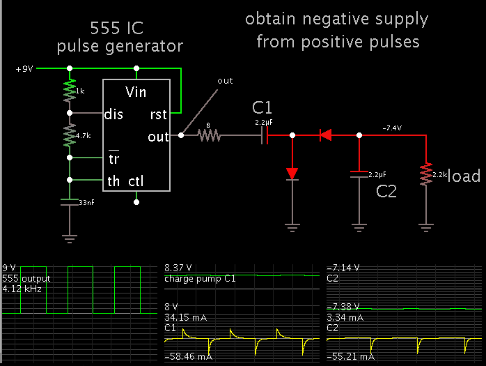
can anybody explain about the operation of the charge pump circuit?i know use of charge pump capacitors in max 232.but i couldn't understand the operation of the charge pump.....

the main purpose of charge pump capacitor is double the voltage and also inverting the voltage.......
how it is happening?
 

It's simply a case of sequencing switches so that the capacitors are first connected across the 5V supply, given time to charge up then disconnected and rejoined in series with the supply. RS232 (or more accurately 'V24') needs the higher voltage on it's communcation wires to work properly and the charge pump is there to make design easier. Older devices without a charge pump needed a +12V and -12V supply to them.

Brian.
can u please explain it very clearly?pls...
 

What he said is MAX232 is used to convert TTL to RS232. TTL works at 5V. RS232 at 12V. Charge pump is a kind of DC to DC converter which increases the voltage. You need to get 12V at the RS232 side and that 12 V comes from 5V supply. Maybe my explanation is not 100% correct.

It's simply a case of sequencing switches so that the capacitors are first connected across the 5V supply, given time to charge up then disconnected and rejoined in series with the supply.

When capacitors of charge pump circuit is connected to 5V it charges upto 5V and then disconnects and connects with the RS232 side to provide 12V at the RS232 lines.

https://en.wikipedia.org/wiki/Charge_pump

https://en.wikipedia.org/wiki/MAX232
 
Last edited:

A video is worth a million words. Take a look at my Youtube video which is an animated simulation of a simple charge-pump voltage doubler.

https://www.youtube.com/watch?v=3czj7J_FE_k

It shows capacitors charging and discharging. It shows current bundles traveling through wires.

Several of my videos portray voltage multipliers which make use of charge-pump capacitors.


Thank u very much Mr.BradheRad...Its really helped to me.do u have any videos analogous to that video?if u have any please post the link.....
 

Thank u very much Mr.BradheRad...Its really helped to me.do u have any videos analogous to that video?if u have any please post the link.....

Since your initial post mentioned the idea of inverting the voltage, this is another configuration which derives a negative supply from positive DC pulses.

The 8 ohm resistor is not needed, but it represents some amount of internal resistance in the preceding stage.


And if looking is helpful, participating is better yet.

The simulator above is not mine but Falstad's. Free to download and use at falstad.com/circuit.

Click the link below to open his website, load my schematic into the simulator, and run it on your computer.

Circuit Simulator

You can watch current moving at proportionate speed in the wires. To have multiple scope traces is especially informative.

You can alter the speed of the simulation.

You can change values by clicking on a component, and selecting Edit.
 
Last edited by a moderator:

Status
Not open for further replies.

Similar threads

Part and Inventory Search

Welcome to EDABoard.com

Sponsor

Back
Top