Continue to Site

Welcome to EDAboard.com

Welcome to our site! EDAboard.com is an international Electronics Discussion Forum focused on EDA software, circuits, schematics, books, theory, papers, asic, pld, 8051, DSP, Network, RF, Analog Design, PCB, Service Manuals... and a whole lot more! To participate you need to register. Registration is free. Click here to register now.

Any idea about digital potentiometer

Status
Not open for further replies.

Narmu

Newbie level 6
Joined
Oct 13, 2013
Messages
13
Helped
0
Reputation
0
Reaction score
0
Trophy points
1
Activity points
104
hey guys, i m really in need of help....can someone explain me wat digital potentiometer actually does..i have no idea about microcontrollers...the project that i m doing is programmable gain amplifier. The specifications given to me are

-> gain has to be varied from 10 to 100
-> cmrr of 100dB
-> gain has to be varied using digital potentiometer
In this I have build a normal instrumentation amplifier where the gain can be adjusted using a pot-lin. But in this I have to make use of digital potentiometer. Can you give some suggestions on it?
 

Basically a digital potentiometer acts as a potentiometer with the wiper position (tap) determined by a binary digital input. Thus an 8-bit digital pot would have 256 equally spaced taps along the resistance element. The tap selected is determined by the value of the binary input. Note that, unlike a standard pot, a digital pot has limitations as to the voltage above the (digital control) ground that can be tolerated.
 

If you have no idea about microcontrollers, that would rule out SPI and I2C digipots.

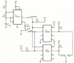
The other digipot command protocol is a three-line device. Essentially, it has a select line, up/down line, and clock line. With a 555 a you can create the control signals.
Back in 1989, I did a simple stereo volume control like that, see attached file.
 

Attachments

  • digipot.GIF
    digipot.GIF
    16.4 KB · Views: 76

You can get analogue transmission gates (like switches) - type 4066, you can control these with digits to open and close, so you build a selection of them to switch in series resistance in your signal path and shunt resistance. Typically with a logerithmic ratio, so S1 does - 1dB, S2 -2 dB, S3 - 4 dB S4 - 8 dB, So by selecting which switches are open and closed already you have a 0 - 15 dB attenuator, add a few more switches, make the range lower so S1 is .5 dB. . . you can design what you want.
Frank
 

Status
Not open for further replies.

Similar threads

Part and Inventory Search

Welcome to EDABoard.com

Sponsor

Back
Top