Continue to Site

Welcome to EDAboard.com

Welcome to our site! EDAboard.com is an international Electronics Discussion Forum focused on EDA software, circuits, schematics, books, theory, papers, asic, pld, 8051, DSP, Network, RF, Analog Design, PCB, Service Manuals... and a whole lot more! To participate you need to register. Registration is free. Click here to register now.

[SOLVED] RS485 signal transmission - LED panels

Status
Not open for further replies.

martin69

Newbie level 3
Joined
Oct 13, 2013
Messages
3
Helped
0
Reputation
0
Reaction score
0
Trophy points
1
Activity points
45
Hi everyone,

I'm trying to build large LED panels (3x128 LED modules) using WS2801 LEDs, with data coming from a Teensy 3.0 microcontroller. I'm having difficulties transmitting my Data and Clock signals between the different panels. The three panels have a separate power supply, so I can't transmit my signals directly because of ground problems.
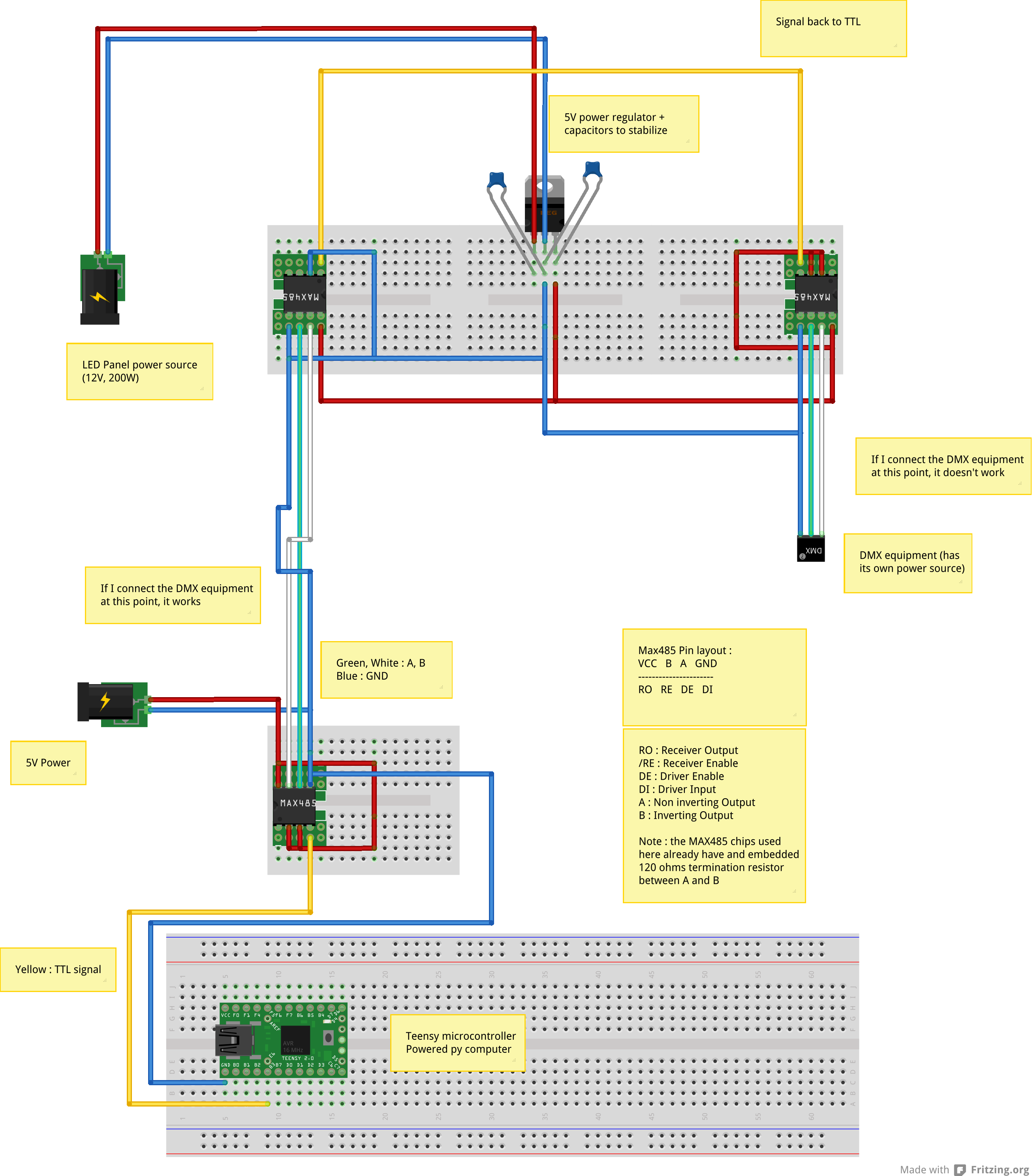
I want to transmit my signals using RS485, so I got myself MAX485 chips, and am using them to symmetrize my signals. So far, it works without any problem if I want to get my signal to the first panel (Teensy output TTL -> Max485 => (RS485) => Max485 -> TTL).
However, when I want to get my signal to the following panel, I'm having a problem. I want to get Clock and Data coming out from the last LED, and RS485 them to the next panel - and this is precisely what does not work. What I want to do is : Teensy output TTL -> Max485 => (RS485) => Max485 -> TTL -> Max485 => (RS485) => Max485 -> TTL.
I know RS485 is in fact a 3-wire system, and I do have a common ground routed from my microcontroller.
I was thinking it might be a ground problem, but I don't know exactly where my problem comes from, since my reception MAX485 and my emission MAX485 are all powered by the same 12V power going to the LED (brought down to 5V, using a LM7805 regulator).

Note : the signal and clock signals output by my last LED are correct, if I route them directly to the following panel, it works alright, but I'm getting artifacts when all 3 panels are connected - that's why I switched to RS485
 

It could be noise or differences between ground potentials but I suspect the real problem is one of data collisions or module addressing. Just for clarification, are you daisy chaining the modules (mod1 -> mod2 -> mod3...) or are you driving them in parallel with the same data wires linked to all three modules? RS485 is designed to be 'multi-drop' where parallel modules can share the same wires but to implement that you have to add a method of avoiding a situation where two transmitters are active at the same time on the bus. If you simply want to use differential data to avoid ground differences between modules, I find it better to use RS432 instead. It has all the electrical advantages of RS485 but uses different wire pairs for outgoing and incoming data, it also works well with cheap CAT-5 network cables!

Brian.
 

Thanks for your answer,

I am indeed daisy chaining the three panels, it is a uC -> panel1 -> panel2 -> panel3 configuration. Each LED works as a shift register, so I need to be in a daisy chain configuration to get my data to the next panel.
What I don't understand is that there shouldn't be any conflict between my different lines : the RS485 is only between each panel, and on each line, there is only one transmitter (or rather 2, but on separate pairs, Clock Out, and Data Out of the last LED of the previous panel), and only one receiver (Clock In, Data In of the following panel). The communication is half duplex, and at no moment the transmitter becomes receiver (likewise for the receiver). In this case, wouldn't it be similar to RS432 ?

Martin
 

Can you post the schematic of your interface please.

From what you are describing, it isn't true RS485 protocol but you are using MAX485 ICs as differential drivers and receivers in a synchronous serial link. True RS485 would be full duplex and asynchronous. It's a perfectly valid use of the devices though and it should work. Next question: I presume there is a 'host' device feeding information to the start of the chain, does it get received and retransmitted untouched at each module or is the data being received and processed before it is sent to the next module? What I mean is, if you removed all the circuitry in the modules except the MAX485 and power supply to them, would data still pass through or is it manipulated in any way before re-transmission?

Brian.
 

The host device feeding information to the start of the chain is a Teensy 3.0 microcontroller, connected to (and powered by) my computer. The information is received correctly by the first panel (I can display stuff). Each LED acts as a shift register (WS2801 LED modules), so yes, the data is received and processed, which is why I can't have all panels wired in parallel

I did a test using DMX equipment to check if I had the same problem with a much simpler configuration : DMX is based on RS485, so it is essentially the same thing.
The fun thing is that I have the exact same problem, so it might not be a complicated problem linked to the LEDs disrupting the phase between data and clock or the like.
If I have microcontroller TTL -> RS485 using the transmission MAX485 -> DMX equipment, it works perfectly.
If I have TTL -> RS485 using the transmission MAX485 -> TTL using the reception MAX485 on the panel -> RS485 using the transmission MAX485 on the panel -> DMX equipment, nothing works. It does look like some data (though it could be just gibberish) might come through some way or another, because the signal input LED on my DMX equipment sometimes lights up.
Here's the schematic I used for this test.


It could be a problem with ground, I wonder ? The panel is powered by a 12V 200W supply, and the Max485 on board are powered by a 5V LM7805 regulator which is linked to it. The transmission Max485 around the microcontroller are powered by a 5V power supply. I connected the ground between them.

Martin
 

I don't think it's a ground problem but I can see some things that are not quite right.

1. You should have capacitors across VCC and GND on each of the MAX485 ICs like you have one the regulator, I suggest 100nF. Incidentally, the input of the regulator should also have a larger capacitor if the 12V feed to it is more than a few cm long, I suggest 10uF in parallel with the 100nF.

2. The top left MAX485 is always in receiving mode so pin 2 AND pin 3 should be grounded. Never leave inputs unconnected unless the data sheet specifically states you can do so.

3. For short distances and only a few devices the wiring type isn't too critical but if you are using wires longer than say 25cm you should use twisted wires between the MAX485s.

4. Please check the terminating resistors are present in your devices, they are not normally internal in the MAX485 otherwise you wouldn't be able to chain many together before they run out of drive capability. Normally you only add one resistor at each end of the bus regardless of the number of 'drops'. I doubt with only two devices using the two-wire connection this a problem though.

My guess is suggestion 2 is the culprit.

Brian.
 

Status
Not open for further replies.

Similar threads

Part and Inventory Search

Welcome to EDABoard.com

Sponsor

Back
Top