Continue to Site

Welcome to EDAboard.com

Welcome to our site! EDAboard.com is an international Electronics Discussion Forum focused on EDA software, circuits, schematics, books, theory, papers, asic, pld, 8051, DSP, Network, RF, Analog Design, PCB, Service Manuals... and a whole lot more! To participate you need to register. Registration is free. Click here to register now.

Problem in Rf communication using ASK 434Mhz

Status
Not open for further replies.

embpic

Advanced Member level 3
Joined
May 29, 2013
Messages
742
Helped
80
Reputation
160
Reaction score
77
Trophy points
1,308
Location
india
Activity points
5,213
Hello masters
I have purchased RF module which is like **broken link removed** and i have two such modules and tried both using simple UART based protocol. But facing problem. So, help me to do communication.
My UART communication work fine and checked on hyper terminal.
i have attached circuit diagram in short images as follows.
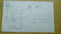
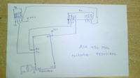
 

You have Tx and Rx connected to two similar uC boards for bi-directional RF communication between two boards. Right? If board sends data through RF then both receivers on board A and board B will receive the same data. Do you avoid this in code? Or is it that you have only one board and posted two images of the same board?

Edit: Remove the connection between the Rx and Tx ANT pins. Connect a 17 cm wire as antenna one for Rx and another for Tx modules.
 
Last edited:

Hi,

You do not say what your 'problem' is ?

Probably you are picking up loads of other signals on the same frequency so your receiver program has no idea what signals come from your transmitter.

You usually have to use 'Manchester Encoding' with those modules.
 

Since he writes that his setup is 'working fine' with hyperterminal, but there is a problem with the uC, then presumably its the uC and its software which is suspect.

How the OP decided there's a problem, is not clear
There is no other I/O shown anywhere, nor his code, nor a description of the problem, nor anything else.
 

i have connected this rx and tx for one controller only. because i was tried with two sepiarate controller then also it giving problem. i think it would be better to solve problem of rf communication.
when i connect rx and tx together then also works fine.and on hyper terminal also giving right information n that basis my UART works fine.
as i told my code works fine no matter i will post my code soon and i think that it's matter of rf communication thats why i shown only things which is needed in circuit diagram.
 

Hi,

But you have not said What happens when you send data though the ASK modules, do you receive any data ? - is some if it complete or is it all rubbish or simply nothing seems to come through ?
Assume you are displaying the received data on an LCD or similar ??
 

when i send data using rf module then data is not received at receiver. as i shown in diagram i have connect tx pin of controller to transmitter and rx pin to receiver.
for reference i have attached my code and program do

it transmit continous letter 'a' with delay
and received letter is shown on lcd.

controller is used is 6 clock per MC.
 

Attachments

  • Rf_communication.rar
    9.4 KB · Views: 75

yes sir but my UART communication works fine.i have problem with RF communication.
 

when i send data using rf module then data is not received at receiver. as i shown in diagram i have connect tx pin of controller to transmitter and rx pin to receiver.
for reference i have attached my code and program do

it transmit continous letter 'a' with delay
and received letter is shown on lcd.

controller is used is 6 clock per MC.

Hi,

Seem to remember when I used those modules, if I started the receiver it displayed all sorts of rubbish/received data even before I transmitted any data to it

Basically it was picking up all the other signals on that frequency.

Would suggest you search this forum on these ASK modules and 'Manchester Encoding' as its a subject that been covered many times before.

Cannot comment on your code as I do not do C .
 

Somebody had a similar circuit but it was not bi-directional communication. He had two uC boards and one was Tx board and another Rx board. He had problems if reciver board was powered first. He had solved ny turning ON the transmitter board first and then powering ON the receiver board. UART also needs 100 ms time for stabilization. Add a delay of 3 sec before entering while(1) loop in both codes and see if it works.

Edit: Try pulling up Rx and Tx lines and see if that solves the problem.
 

yes sir i gonna try this one also
but sir all port are pull up by 4k7 resistor array. and about delay i will try this one.
and my tx and rx are on same board
 

.... He had solved ny turning ON the transmitter board first and then powering ON the receiver board. ....

This doesn't seem to be a real 'solution', since somehow the receiver, without being turned on, has to still "know" when the tx has been switched on. And how can it do that ? This is OK for a testing environment where they are both in the same vicinity, but the whole purpose of such a system is usually unattended operation and distance separation etc etc.
 

Or i have to try using Encoder and decoder for rf transmitter and rf receiver?
but i don't have that much pin counts.
 

Hello masters
I have purchased RF module which is like **broken link removed** and i have two such modules and tried both using simple UART based protocol. But facing problem. So, help me to do communication.
My UART communication work fine and checked on hyper terminal.
i have attached circuit diagram in short images as follows.


Hello,

What is the baudate you are using ? I think the maximum is about 2000 bits/second for the cheap
TX/RX pair. They are designed for remote control of doors,alarms in cars etc.

You can find tx/rx pairs than can work up to 150kb/second and they are much more expensive.
So the advice here is lower the baudrate to a minimum,and see if that works.

Good luck.
 

Hello sir i had tried with 600 bits/second ,still this one is not working even i had tried with lowest and step by step upto 2400 bits/second.
 

Hello sir i had tried with 600 bits/second ,still this one is not working even i had tried with lowest and step by step upto 2400 bits/second.

How do you know its not working ? i.e. what indication is there in your setup which says working/ not working ?

Also as per your diagram, you have not connected some of the Rx pins - Vcc and Gnd on the right side. Connect these just to be sure.
Next : you have connected the Tx antenna directly to the Rx antenna. This is probably causing trouble. Disconnect this wire.

Lastly: what is the code running in your uC ? Ah, i see you have posted some C code, but the flag's and isr's look messy. Maybe you should rethink your code to be a little simpler.

A bit of structure in your experimenting, and a slightly better way of reporting here will help both yourself as well as forum members understand w t f is going on with your setup.;-)
 
Last edited:

Just connect Transmitter to uC and send continuous data like 'K' then connect receiver o/p to TTL input of TTL to RS232 or TTL to USB adapter and plug the RS232 or USB side of the converter to PC and see if you get the data transmitted in PC. Use RealTerm for capturing data. If it works then connect Transmitter input pin to TTL to RS232/USB converter and send data from PC. Connect receiver to uC Rx pin and blink LED if proper data is received. Just test step by step. You will come to know whether transmitter or receiver or both working or not working.
 

yes sir i am sure that vcc and ground connection is there and also check voltage between vcc and ground.
this set up is not working as i am transmitting data but receiver is not receiving the data.
and about antenna i tried using wire also separately.
 

Status
Not open for further replies.

Similar threads

Part and Inventory Search

Welcome to EDABoard.com

Sponsor

Back
Top