Continue to Site

Welcome to EDAboard.com

Welcome to our site! EDAboard.com is an international Electronics Discussion Forum focused on EDA software, circuits, schematics, books, theory, papers, asic, pld, 8051, DSP, Network, RF, Analog Design, PCB, Service Manuals... and a whole lot more! To participate you need to register. Registration is free. Click here to register now.

How to design a simple constant current load

Status
Not open for further replies.

long88

Member level 3
Joined
Nov 14, 2010
Messages
60
Helped
1
Reputation
6
Reaction score
3
Trophy points
1,288
Activity points
1,762
Hi All,

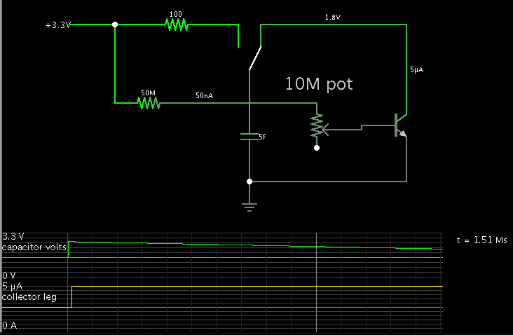
Recently , i am doing some test with the super capacitor. My objectives was to prove that the time taken to discharge a super capacitor from 3.3 - 1.8 v is equal to my calculation results.
Let assume that the current discharge to my load is constant at 5uA. The capacitor is 3.3v and 5F.
Based on my calculation, the time taken for a capacitor voltage drop from 3.3 - 1.8 V is 2500000 seconds.

However, the current drop will always drop if the voltage drop. I need a circuit that can withdraw constant current within the voltage range of (3.3 - 1.8v). Is anyone can recommend me some simple constant current load?
THank you very much.


A transistor will draw an unchanging current from the supercapacitor, if you are allowed to control it via an unchanging bias from the 3.3 V supply.

Screenshot:


The simulation began with the 3.3V supply charging the capacitor. Then the switch was thrown to discharge the capacitor.

Current drain is a constant 5 uA.

The scope trace shows the declining cap level as a linear plot.

The time marker (lower right) indicates the time to drop to 1.8 V is 1.5 Msec.
 

question regard supercap discharge time.png

Thank for the reply. Anyone got experience to calculate the discharge time for a supercapacitor. Please advice me whether my calculation is correct. Thank you.

thx godfreyl and BradtheRad ,
I will do a high current source to test it .


- - - Updated - - -

Hi BradtheRad,

1.51 *10^6 s right ? can share with me what simulation software u use? i need to prove that the practical and theoretical result are identical
Thank you very much
 
Last edited:

My calculations says it was 1500000 secs (I think the same shown in simulation also)....
Code:
Q = C * V

Q1 = C * V1

   = 5 * 3.3

   = 16.5 c


Q2 = C * V1

   = 5 * 1.8

   = 9 c

The decaying rate(I) is 5 uC/S 

so T = ( Q1 - Q2 ) / I

     = (16.5 - 9) / 0.000005

     = 1.5 Ms (*No losses included in the calculation)
 

Hi Venkadesh_M,

I think my calculation formula is a bit different from you, but the result is same . If my MCU constantly withdraw 3uA, then the time taken will be 2.5 Ms if not losses is considered.
I need a actual hardware and software to simulate it. Thx you very much
 
Last edited:

Use a 555 IC with you super cap and additional const current discharging circuit you could see between 2/3Vcc and 1/3Vcc,or use a comparator to show the output....
There are so many simulation softwares available in internet....

And also the theoretical calculation is correct and It will surely work for short timing..
consider tolerance in capacitor and current source values when doing in Hardware and Test the current source with possible input voltages for stablity...
 

HI Venkadesh_M,

What this means =>the theoretical calculation is correct and It will surely work for short timing..?
In fact if we consider the leakage current and capacitor tolerance, it will still able to last at least one week right ?
 

If you choose the delay to go for an hour means the calculated timing will exactly attained because the effect of leakage current is low....
lasting for 1 week is depend on the capacitor you choose, If the leakage current is very very low surely It will be so....
Try to include that also in the calculation....
 

so you means the leakage current will be increase as the delay increase ? . i am using two super cap with 10F and connected in series.
link: https://sg.element14.com/panasonic/eechz0e106/capacitor-10f-2-5v/dp/1673323
How to consider the leakage current. As i dont get this information from the datasheet

I have done the transistor circuit as mention by BradtheRad, but the current to the transistor will drop as the V cap drop also.

Thank you very much.
 

All electrolytic capacitors have a leakage current when a direct current is applied. Th
is leakage current depends on time, voltage, and te
mperature. After long dead storage this
leakage current will increase and, for a short time, can be
10 times greater at the time of reuse. The ca
pacitor will not be damaged and its li
fe expectancy will not be impaired if
the rated voltage is applied directly after long storage. In
general, the expected continuous operating leakage current will be re-attained or fall below its value after about
30 minutes. Any operation below the rated voltage will result in a significantly lower leakage current

The leakage current is not constant, I mean if you shorten your test time the effect of leakage current will be low and you can test your method of calculation exactly.....

The characteristics of current source is very important because the small variation in the amplitude could lead you completely different timing so first choose and test a constant current circuit.....


Design a transistor with very good output characteristics
untitled.JPG

You need it to be constant over the desired range dont use any emitter resistor..
 
  • Like
Reactions: long88

    long88

    Points: 2
    Helpful Answer Positive Rating
Thank VenKadesh_M,
I have try to redesign the transistor circuit, and it work very accurate if compare to the theoretical calculation. My transistor will constantly draw 15.5 mA if the Vcap is within range 3.3 - 1.5v.
In fact, my objective was to design a circuit that will allow MCU (PIC18F) to operate in normal and sleep mode for a long period (3 month - 6 month) if the power supply fail function. As the Vcap drop accordingly , the current consumption for the MCU will drop accordingly as the Vcc drop. Am i right? The time taken for normal mode and sleep mode can be known from my firmware. But i really can't figure out the relationship between i(t) vs Vcap(t).
What is the formula or correct method to define the working duration of MCU working with super cap? thank you
 

I think your application is to power a micro controller with super cap and you are going to work on it to find how much timing it can power it... Basically the current taken by a controller is not constant it depends on power mode, Vdd, process, output states, direct output devices and so many things so you can not relate between Its voltage and current..
You have Two choices..

One is taking a real time test with the controller as it was and measuring the sleep mode + normal mode (It would take a week or month)

second is to pre determine it...
Measure the following things
1, current taken by MC in 3.3V normal mode with all its output connected..
2, current taken by MC in 1.8V normal mode with all its output connected.. (I assume that it was the lowest voltage the Mc can operate)
3, current taken by MC in 3.3V sleep mode with all its output connected..
4, current taken by MC in 1.8V sleep mode with all its output connected.. (If you take another reading for 2.5V will be more than enough)
with this readings we can find How much time a MC can be powered by the super cap..
 
  • Like
Reactions: long88

    long88

    Points: 2
    Helpful Answer Positive Rating
Hi BradtheRad,

1.51 *10^6 s right ? can share with me what simulation software u use? i need to prove that the practical and theoretical result are identical
Thank you very much

I used Falstad's animated simulator.

Free to download and use, at:

www.falstad.com/circuit
 
  • Like
Reactions: long88

    long88

    Points: 2
    Helpful Answer Positive Rating
Hi Venkadesh_M,
Yup. That is my purpose. Real time test consume too much of time so i think it was not a right choice for me.
I think the second option look good for me .

Thank you very much.
 

Irunmode VS Vs.pngIsleepmode VS voltage .png

Hi All,
I found this information from the pic datasheet. It show me the relationship for current (sleep mode and normal mode )vs Voltage range of Vcc. Based on this information, i can assume the current consume for a micro controller while there is a drop in Vcc.
Since i know the current consume and the voltage drop, i may use the equaltion C(dv)/I(t) = dt to calculate time taken for discharging capacitor from Vcc till Vn. Please advise me whether my concept is correct.

My main objectives was to determine how long a MCU can last if the Vcc was replaced with a full charge super capacitor. I can calculate precisely the timing for MCU sleep mode and MCU normal mode.

Thannk you
 

Hi Venkadesh_M ,
Thank you very much.
Just another question. In market,there must be some product built in with a super capacitor as a back up battery. They will sure put the duration of how long the super cap can last before the device is turned off. They also using this kind of methods to estimate the discharge time of super cap? or there is an more accurate or professional method to determine it. Thank you very much.
 

When using the word battery It will come under Ampere hours... They will be rated with mAH.. for example a 3.3V 100mAH battery can give 1mA for 100Hours in fully charged state...!
 

Hi Venkadesh_M ,

I can't assume my super cap work as battery. Am i right ? As capacitor is a not linear device which means the voltage drop will first cause my hardware to shutdown. But battery with abilities to maintain same voltage level for long period.
My boss not agree with the way i calculate the time of discharge super capacitor.
Any alternative methods to solve this issue, i already study the cap function this two days. But i really can't derive a new formula that work to determine the time taken of a discharge capicitor. I am super headache now. thank you

Best regards,
Chen Long
 

Status
Not open for further replies.

Part and Inventory Search

Welcome to EDABoard.com

Sponsor

Back
Top