Continue to Site

Welcome to EDAboard.com

Welcome to our site! EDAboard.com is an international Electronics Discussion Forum focused on EDA software, circuits, schematics, books, theory, papers, asic, pld, 8051, DSP, Network, RF, Analog Design, PCB, Service Manuals... and a whole lot more! To participate you need to register. Registration is free. Click here to register now.

[SOLVED] Odd behavior for a simple circuit.....

Status
Not open for further replies.

stephr1

Newbie level 4
Joined
Dec 12, 2009
Messages
5
Helped
0
Reputation
0
Reaction score
0
Trophy points
1,281
Location
Bay Area, CA
Activity points
1,372
Hi all,

I can't remember if I've actually posted here before, but know I have visited a few times looking for help.

Here's an interesting problem I've run into. Hope someone has some good analog insight (my primary expertise is in digital).

I have built a front end amp that's supposed to go to 200MHz (I only need it for 100Mhz). The amp seems to work (it's a borrowed design...did I mention I'm a digital kind of person? ;) for the most part (Been using an older, good condition HP 183 w/200MHz 4-Ch vert. amp).

While the amp has some front-end switching options (x1/x10, low-pass filter, AC/DC, etc.) implemented thru relays, I have not yet installed those parts.

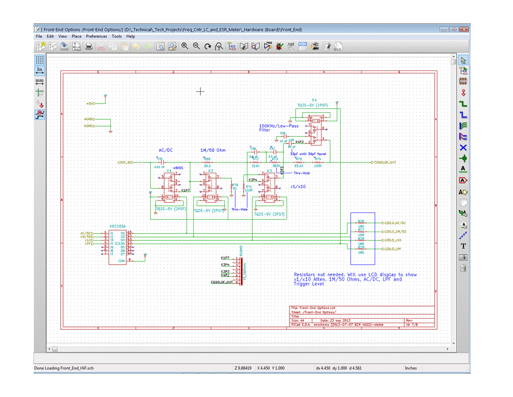
Here's what I've got: Using the cal output on the scope (2KHz and 1MHz options @ .5V or 50mV), the amp and circuitry work great @ 2KHz. At 1MHz, tho, it seems a little odd. Imagine the input simply being a .01uF cap (for DC, this cap is shorted out) in series with 26.1 ohm resistor in series with a 93.1 KOhm resistor (the rest of the circuit doesn't really seem to matter with this problem).

At both 2KHz and 1MHz I can see fairly clean signals at the cap (1 side is signal in), 26.1 Ohm resistor and the side of the 93.1K that connects to the 26.1 Ohm resistor. However, when I go to the other side of of the 93.1K resistor, the 1MHz signal turns into a triangle wave (almost like the square wave is being integrated) and is much smaller in signal level.

At first I thought it might be some freq issue in the circuit after the 93.1K (goes to a 100K after which the signal is split to a 10M resistor/FET one way and ~500K resistor to an op amp input the other way). So I disconnected the 100K which left 1 side of the 93.1K open. Same results on the open end of the 93.1K resistor. Replaced the resistor (SMD) with another SMD (thinking it might be some inductance issue w/the resistor) and then tried a 1/4 watt axial. Same results.

Thought it might be the scope probe. 10M low-cap input. Same results on either of 2 probes, in any of the 4-ch of the vertical amp (BTW - Any probe/ch shows a clean 1MHz signal from the cal output).

My sense is there could be some unseen interaction with the circuit (only 3 passive components, tho) and the scope, but did I mention my background is digital.

I could sure use some help, suggestions and/or insight on this.

Thanks in advance.

Cheers...Steph
 

Two points.

1. I think that the details of your post can be much better (or at all) understood with a schematic.

2. Apparently you are measuring at high impedance nodes in your circuit with a regular oscilloscope probe. The results are effectively meaningless for high frequencies. E.g. a 93k resistor loaded with a 12 pF probe input forms a low-pass with 150 kHz cut-off frequency. A square wave looks about like a triangle after passing it.
 

Update: I put the circuit back together and checked at the output. The amp itself seems to be working correctly because the signal (either 2KHz or 1 MHz) I see at the lower impedance output is pretty much what I see at the "trouble spot" :( I did discover I had been connecting to a point I thought was ground but turned out to be the wrong end of a 51 Ohm res. Getting to the right connection didn't matter (at least, not as much as I could tell).

Out of curiosity, I did some resistance checks around the circuitry and found another odd point (tho, not close to where my initial problem seems to reside). On a connection between a number of parts in the actual amp section (including FET and followon BJT) I found the connection between all the parts (and from one end to the other) to be near 0 ohms (or as close to it as my meter reads). However, from different parts of this connection down to ground I found very different readings. On 1 section, it measures ~500-1500 ohms. In another section (same wire supposedly 0 ohms away) I get ~380K. Need to sort this one out.

It makes sense that the scope probe does indeed seem to cause measurement errors in the high impedance circuits. However, I suspect something else is going on from the "construction side" of things that I need to check out.

However, I'm still open to suggestions that may come to mind :)

Again, thanks and cheers...Steph

@FvM

Thanks for the quick reply! I should have suspected it was something I overlooked :(

1. I'm using KiCad for the schematic capture and I have yet to figure out how to do pdf. However, let me try it here:

------------.01uF---26R1------93.1K
Signal In -> -||---/\/\/\/\/---/\/\/\/\/--- -> (As I mentioned, this splits into 2 circuits)
Freq/Qual
2KHz-------G---G----------G---------G
1MHz-------G---G----------G---------B!!

Hope this is understandable. G=good signal, B=bad
Where the letters are located under the circuit indicate the good or bad measurements I'm seeing at that point.

2. As I said above, if I did the math.....the 2 probes I have are 10pF and 14 pF, both @ 10M Ohms. @10 pF, looks like a reactance of ~16K. Combined w/93.1K in series, looks like signal is reduced to ~15%. Fairly consistent with what I've been seeing. And then considering rolloff up to 1MHz...that's my triangle :(

I assume that if the output at this point was 50-100 Ohms, I wouldn't be seeing what I do. I suppose I could pull the 93.1K down to ground with a value that would "neutralize" the cap reactance (like 50/100 Ohms up to ~1.6K) and adjust my expectations as to the output level (really small?). The output of the amp itself is 232 Ohms (complimentary transistors driving into a 178 Ohms series resistor pulled to ground by the 232). I thought I had lost the signal there, but maybe I got confused :(

Any other suggestions on how I get around this problem given the probes I have?

Vielen danken und cheers...Steph


Two points.

1. I think that the details of your post can be much better (or at all) understood with a schematic.

2. Apparently you are measuring at high impedance nodes in your circuit with a regular oscilloscope probe. The results are effectively meaningless for high frequencies. E.g. a 93k resistor loaded with a 12 pF probe input forms a low-pass with 150 kHz cut-off frequency. A square wave looks about like a triangle after passing it.
 
Last edited:

Good that some measurement details are understandable. I must confess however that I don't yet understand what - beyond measurement artefacts - the real circuit problem is, or if there's any problem at all.
 

My sense is that there does seem to be some kind of problem at the higher freq (layout, marginal part, etc.)....just not sure what that is yet. Here's why I think so:

Both 2KHz and 1MHz signals look fine until the 1MHz doesn't on the "other side" of the 93.1K. I now better understand this is due to impedance issues (thanks for the insight on this!). However, going to a low impedance point in the amp section (mainly output @ 232 res., but I have a few other low impedance points I can check), the 2KHz signal looks great. The 1MHz signal is a triangle wave.

So, there is a problem. I'll need to refresh my analog theory knowledge and go at it again. I'll also come up with some kind of signal gen so I can get an idea the freq where this begins to happen. I'll post back if/when I find the cause.

Again, I appreciate the help.

Cheers....Steph

Good that some measurement details are understandable. I must confess however that I don't yet understand what - beyond measurement artefacts - the real circuit problem is, or if there's any problem at all.
 

My sense is that there does seem to be some kind of problem at the higher freq (layout, marginal part, etc.)....just not sure what that is yet.

Could be of course. But we know effectively nothing about the circuit on the other side of the 93k resistor. There won't be a node with an impedance in this order of magnitude in the signal path of a 100 MHz amplifier, because you can't realize a respective low capacitive load on a PCB.
 

I'm using KiCad for the schematic capture and I have yet to figure out how to do pdf.
How about "Print Screen", then paste into MSPaint and save it as a GIF? Works for me.
 

D'oh!! :( I'm so used to going directly to pdf out of MS Office I forgot that I could use it as an intermediate step :(

OK. Attached 2 gif files of the schematic (hopefully they're readable) due to the nature of KiCad. And it's a work in progress.

Some notes: page 1 is the input conditioning circuit. The output CONDLOF_OUT goes to page 2, Amp In. Only a few of the passive components (i.e. none of the relays) have been installed. C36/C37/R72/R73 are shorted out (x1) for my testing. The side of R75 that connects to R74 is where I see the problem with the 1MHz signal. The most likely culprit (@ 1MHz) here seems to be the combo of R75 coupled w/impedance of the scope.

Page 2: Fully implemented and, as I said, seems to be operational with a 2KHz sig (still need to test freqs between 2KHz and 1MHz).

Page 1 & 2: Ignore the vertical-like drawings at the bottom of the pages. I had been messing around with some layout ideas that I have since discarded, but have yet not updated the drawing.

Thanks for catching anything that might be of help.

Cheers...Steph


How about "Print Screen", then paste into MSPaint and save it as a GIF? Works for me.
 

R75 - R74 forms a low-frequency path. The high frequency path is through the parallel connected 39 pF capacitor. You can better tap the full bandwidth signal at the right side of R74.

Accessing the sensitive circuit nodes with a regular oscilloscope probe will however disturb the well balanced frequency compensation, so the 1 MHz squarewave won't be perfect in the measurement. If everything is assembled and setup correctly, the correct waveform will be reconstructed at the ouput of the composite amplifier.

If KiCad doesn't provide own PDF output, installing a freepdf printer driver should allow you to generate better printouts.
 

Update: 1 quick note....I found an 80MHz oscillator (TTL) and hooked it up. Sig out looked pretty much like sig in, so I'm back on track to finish up this design. Now I can mount the relays and on to conversion and other control circuitry. Happy camper :))))

Problem solved. Thanks much for the help!!

I'd call this a D'oh! moment, but not all of it ;)

I had been looking at the board and realized I had mounted C39, but only connected 1 side (the partial D'oh!) because I had held off mounting the relays (where the other side of C39 goes to....C39 is switched out and C36 switched in for a 100KHz LPF...essentially what I had with C39 unconnected). As soon as I read your reply below, it was obvious to me that cap was needed. When I connected it (C39) up (temp hardwire), it worked like expected. I've tested @ 2MHz (clock gen device) and now will try for something closer to 100MHz and see what happens.

I knew the amp was working, just forgot an important connection :( At 2MHz, it's not the most perfect signal, but it looks pretty good.

My sincere appreciation for the help!!

Cheers...Steph

R75 - R74 forms a low-frequency path. The high frequency path is through the parallel connected 39 pF capacitor. You can better tap the full bandwidth signal at the right side of R74.

Accessing the sensitive circuit nodes with a regular oscilloscope probe will however disturb the well balanced frequency compensation, so the 1 MHz squarewave won't be perfect in the measurement. If everything is assembled and setup correctly, the correct waveform will be reconstructed at the ouput of the composite amplifier.

If KiCad doesn't provide own PDF output, installing a freepdf printer driver should allow you to generate better printouts.
 
Last edited:

Status
Not open for further replies.

Part and Inventory Search

Welcome to EDABoard.com

Sponsor

Back
Top