Continue to Site

Welcome to EDAboard.com

Welcome to our site! EDAboard.com is an international Electronics Discussion Forum focused on EDA software, circuits, schematics, books, theory, papers, asic, pld, 8051, DSP, Network, RF, Analog Design, PCB, Service Manuals... and a whole lot more! To participate you need to register. Registration is free. Click here to register now.

Hd44780 serial transmission

Status
Not open for further replies.

cts_casemod

Member level 4
Joined
Dec 9, 2010
Messages
72
Helped
14
Reputation
28
Reaction score
14
Trophy points
1,288
Location
London
Activity points
1,950
Hi,

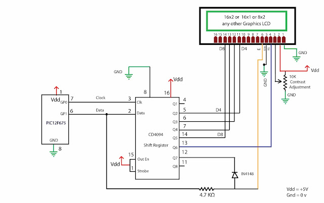
Looking for a way to serially transmit Data to a HD4470 LCD. Both the source and the LCD are parallel.

Easy enough to get a serial LCD, problem is my source is parallel, so I would have to convert that to serial first.

Tks
 

Use a shift register for the parallel-to-serial conversion, e.g. 74xy{165,166,589,597}, or a dedicated chip like NJU3754.
 

Use a shift register for the parallel-to-serial conversion, e.g. 74xy{165,166,589,597}, or a dedicated chip like NJU3754.

And how do I generate the control signals!? I am using 74LS165 with a 1KHz Clock but I can not see a way to generate the enable output and strobe signals (to load data).
Regards
 
Last edited:

Show how you tried to do it!

You have to separate the Load and Shift phases. I guess you have a signal which tells you that a new parallel data word is available (Data Ready, low impulse) - connect it to Shift/Load and Clock Inhibit). After it's gone (log. high again), the data will be shifted out by your clock signal. Perhaps you have to delay the Clock Inhibit signal (e.g. 1 clock period) after Shift/Load going high.

During this serial shift out time (given by a counter or an acknowledgement signal from the serial receiver) you have to inhibit the Data Ready signal. See the Timing Diagram of the LS165 data sheet.
 

3-Wire Serial LCD using a Shift Register
https://www.electronics-lab.com/projects/mcu/015/
https://embedded-lab.com/blog/?p=30

Schematic_1.png


3WireLCDBlock.png


16x2 Serial LCD (Two Wire) with PIC12F675
https://www.circuitvalley.com/2011/12/two-wire-serial-lcd-16x2-graphics.html

Serial-LCD.jpg


Best regards,
Peter
 

Show how you tried to do it!

You have to separate the Load and Shift phases. I guess you have a signal which tells you that a new parallel data word is available (Data Ready, low impulse) - connect it to Shift/Load and Clock Inhibit). After it's gone (log. high again), the data will be shifted out by your clock signal. Perhaps you have to delay the Clock Inhibit signal (e.g. 1 clock period) after Shift/Load going high.

During this serial shift out time (given by a counter or an acknowledgement signal from the serial receiver) you have to inhibit the Data Ready signal. See the Timing Diagram of the LS165 data sheet.

DSCN1273.JPG

This is how I've done it. I have a small PCB that goes where the LCD was originally, supplied by 5VDC from the LCD port. A 555 gives me a clock. I attached this to a breadboard to Analise waveform on the oscilloscope. Basically I need something similar to this. (one of the images is not working but you can click the link. Not sure why).

snes_controller07.jpeg
.
snes_controller12.jpeg


Notice how one of the signals must be given only when the clock is high. So I either need to divide the clock by nine and use a logic gate to only enable when the clock goes high or divide by 18 using some kind of counter and or the outputs I want for a particular signal. But the problem is while using a counter and the counter is shifting inputs if it happens to go low for a fraction of a millisecond then the output turns out to really random values.


I have no idea how to get these signals. A micro-controller seems the logical solution, but I don't know how to program :(

- - - Updated - - -


Peter,

Thanks, but thats not what I am trying to archive. I need to serialize the data from a parallel source before I have a serial stream to decode (so I can use the circuit you provided). The serial bit is easy enough. Clock and signal
 

This is how I've done it.
I didn't mean to show a photo, but a circuit diagram of your current connection. If you don't tell which signals from the parallel data source and from the serial data receiver are available, we won't be able to help you further.

... if it happens to go low for a fraction of a millisecond then the output turns out to really random values.
Is this the bottom osci signal? If so, you have to inhibit it during serial data out. Where to is it connected? Load/Shift?
 

I didn't mean to show a photo, but a circuit diagram of your current connection. If you don't tell which signals from the parallel data source and from the serial data receiver are available, we won't be able to help you further.


Is this the bottom osci signal? If so, you have to inhibit it during serial data out. Where to is it connected? Load/Shift?


Ignore that, the brain cells are in need of some rest ;)

X1600-TEST11-1.jpg

X1600-TEST11-3.jpg

This is the schematic. Everything according to data sheet

What Ive done so far was using a 4017 decade counter to divide the clock by three and or the inputs to the respective signals. I use the clock inhibit to stop serial data output and shift load to load my parallel data, after which I release CI. I get a random output on the serial data. I am sure when the counter switches to the next bit the output is disabled for a fraction of a millisecond
messing things up. Also the whole circuit is quite complex... Isn't there any parallel to serial converter that only needs a clock signal?
 

Is p32 (connected to SHIFT/LOAD) an output signal coming from somewhere (lower trace signal from your osci photo above)? If so, try and connect it to CLOCK INHIBIT (pin 15). May be you have to delay (i.e. stretch) this CI signal for one clock edge, see the 'LS165 TIMING DIAGRAM.

Isn't there any parallel to serial converter that only needs a clock signal?
Any parallel to serial converter needs to know when to reload parallel data. So either your LCD tells you the end of serial data transfer (ACK signal), or you have to use a counter for the 8 (perhaps 9) clocks.
 

I was looking for something without the shift load. That's the biggest pain. I can live with the clock inhibit. Counting is not an issue.

Pin 32 is connected to shift load as you say. They are all timed. The timing doesn't always go well. It has glitches and the output is random.
 

Status
Not open for further replies.

Similar threads

Part and Inventory Search

Welcome to EDABoard.com

Sponsor

Back
Top