kanmaedexandzelbladex
Member level 1
- Joined
- Jul 20, 2013
- Messages
- 35
- Helped
- 1
- Reputation
- 2
- Reaction score
- 1
- Trophy points
- 8
- Location
- Philippines
- Activity points
- 479
Hello Everyone,
I'm planning to measure the audio susceptibility (vo(s)/vi(s)) of my Boost Converter but it's drawing 10A DC current at its input for a full-load output. The 10A DC current has small ripple around 0.6A peak-to-peak. If I put a signal generator on top (in series) with my input DC voltage it will get damaged and the signal generator has a 1A fuse so it cannot be used in this application. I am thinking of some way of doing the measurement by sort of isolating the signal generator? Could this be done in a simple way like with a transformer and some few components without the need for a construction of some amplifier?
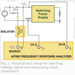
The image attached here I found from **broken link removed** seems to show how to measure input impedance of power supplies without the putting the input AC voltage in series with the DC input. I don't have any Network Analyzers and so I'm planning to do the measurement manually by looking at the oscilloscope.I'm also not sure how the measurement circuit should be designed. The resistor I think is for biasing the transistor to work as a switch?
Thanks
I'm planning to measure the audio susceptibility (vo(s)/vi(s)) of my Boost Converter but it's drawing 10A DC current at its input for a full-load output. The 10A DC current has small ripple around 0.6A peak-to-peak. If I put a signal generator on top (in series) with my input DC voltage it will get damaged and the signal generator has a 1A fuse so it cannot be used in this application. I am thinking of some way of doing the measurement by sort of isolating the signal generator? Could this be done in a simple way like with a transformer and some few components without the need for a construction of some amplifier?
The image attached here I found from **broken link removed** seems to show how to measure input impedance of power supplies without the putting the input AC voltage in series with the DC input. I don't have any Network Analyzers and so I'm planning to do the measurement manually by looking at the oscilloscope.I'm also not sure how the measurement circuit should be designed. The resistor I think is for biasing the transistor to work as a switch?
Thanks
Attachments
Last edited: