Continue to Site

Welcome to EDAboard.com

Welcome to our site! EDAboard.com is an international Electronics Discussion Forum focused on EDA software, circuits, schematics, books, theory, papers, asic, pld, 8051, DSP, Network, RF, Analog Design, PCB, Service Manuals... and a whole lot more! To participate you need to register. Registration is free. Click here to register now.

voltmeter using pic 16f877a problem

Status
Not open for further replies.

madogas

Junior Member level 3
Joined
Nov 4, 2012
Messages
27
Helped
1
Reputation
2
Reaction score
1
Trophy points
1,283
Activity points
1,503
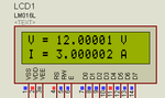
hi i have problem the voltmeter dose not give me right reading when the input is 9 the reading is 30.9 when i test it with avometer across 20k its reads 9 but the lcd reads 30.9 ... help me
Code:
                              // LCD module connections
sbit LCD_RS at RB5_bit;
sbit LCD_EN at RB7_bit;
sbit LCD_D4 at RC4_bit;
sbit LCD_D5 at RC5_bit;
sbit LCD_D6 at RC6_bit;
sbit LCD_D7 at RC7_bit;

sbit LCD_RS_Direction at TRISB5_bit;
sbit LCD_EN_Direction at TRISB7_bit;
sbit LCD_D4_Direction at TRISC4_bit;
sbit LCD_D5_Direction at TRISC5_bit;
sbit LCD_D6_Direction at TRISC6_bit;
sbit LCD_D7_Direction at TRISC7_bit;
// End LCD module connections


char look(int a)
{
   switch(a)
   {
       case 0:
              return '0';
       case 1:
              return '1';
       case 2:
              return '2';
       case 3:
              return '3';
       case 4:
              return '4';
       case 5:
              return '5';
       case 6:
              return '6';
       case 7:
              return '7';
       case 8:
              return '8';
       case 9:
              return '9';
       default:
              return '.';
   }
}


void main()
{

  unsigned int v,vp,ip,i;
  char *volt = "00.0";
  char *current = "0.00";
  TRISA  = 0xFF;
  Lcd_Init();
  Lcd_Cmd(_LCD_CLEAR);
  Lcd_Cmd(_LCD_CURSOR_OFF);

  do
  {

       ADCON1 = 0x00;
       v = ADC_Read(2);
       i = ADC_Read(3);
       i = (i*4.8828)/0.47;
       v = ((v*4.8828)/20)*120;
       if(v!=vp || i!=ip )
          Lcd_Cmd(_LCD_CLEAR);
       vp = v;
       ip = i;
       volt[0] = look(v/10000);
       volt[1] = look((v/1000)%10);
       volt[3] = look((v/100)%10);
       Lcd_Out(1,1,"Voltage = ");
       Lcd_Out(1,11,volt);
       Lcd_Out(1,16,"V");

       current[0] = look(i/1000);
       current[2] = look((i/100)%10);
       current[3] = look((i/10)%10);
       Lcd_Out(2,1,"Current = ");
       Lcd_Out(2,11,current);
       Lcd_Out(2,16,"A");
       Delay_ms(250);
  } while(1);
}

Untitled.jpg
 

Hi there,

Are you sure about this function look(v/10000);??

Code:
 volt[0] = look(v/10000);
       volt[1] = look((v/1000)%10);
       volt[3] = look((v/100)%10);

Code:
current[0] = look(i/1000);
       current[2] = look((i/100)%10);
       current[3] = look((i/10)%10);

for current and voltage division why are you using different logic??

update me,

Best regards.
 

the rang is 0 to 30v and 3A current .
that is right ligo.george but it is not working correct with me idont know why

- - - Updated - - -

the rang is 0 to 30v and 3A current .
that is right ligo.george but it is not working correct with me idont know why
 

this the the project folder
 

Attachments

  • voltmeter1.rar
    223 KB · Views: 62

Try this.


Code C - [expand]
1
2
3
4
5
6
7
8
9
10
11
12
13
14
15
16
17
18
19
20
21
22
23
24
25
26
27
28
29
30
31
32
33
34
35
36
37
38
39
40
41
42
43
44
45
46
47
48
49
50
51
52
53
54
55
56
57
58
59
// LCD module connections
sbit LCD_RS at RB5_bit;
sbit LCD_EN at RB7_bit;
sbit LCD_D4 at RC4_bit;
sbit LCD_D5 at RC5_bit;
sbit LCD_D6 at RC6_bit;
sbit LCD_D7 at RC7_bit;
 
sbit LCD_RS_Direction at TRISB5_bit;
sbit LCD_EN_Direction at TRISB7_bit;
sbit LCD_D4_Direction at TRISC4_bit;
sbit LCD_D5_Direction at TRISC5_bit;
sbit LCD_D6_Direction at TRISC6_bit;
sbit LCD_D7_Direction at TRISC7_bit;
// End LCD module connections
 
float v, i , vp, ip;
unsigned char volt[23], current[23];
 
void main()
{
      TRISA  = 0xFF;
      ADCON1 = 0b10001001;
      CMCON = 0x07;
      CVRCON = 0x00;
 
      Lcd_Init();
      Lcd_Cmd(_LCD_CLEAR);
      Lcd_Cmd(_LCD_CURSOR_OFF);
      Lcd_Out(1,1,"V = ");
      Lcd_Out(2,1,"I = ");
 
      do
      {
           v = ADC_Read(2);
           i = ADC_Read(3);
 
           if(v!=vp || i!=ip ){
 
                 v = v * 30.0 / 1023.0;               //ADC 5V input means 30 V and 1023 raw adc value
                 i = i * 3.0 / 1023.0;                //ADC 5V input means 3 A and 1023 raw adc value
                 
                 FloatToStr(v, volt);
                 FloatToStr(i, current);
 
                 strncat(volt," V",2);
                 strncat(current," A",2);
 
                 Lcd_Out(1,5,volt);
                 Lcd_Out(2,5,current);
 
                 vp = v;
                 ip = i;
 
                 Delay_ms(250);
           }
           
      } while(1);
}


It is showing 30V and 3A when adc inputs are 5V. It is right. There is some other problem. Draw the circuit in proteus and zip and post it here. The circuit is wrong. I is always 0. V is showing 30 V.
 
Last edited:

no the volt that i want to measured is 12 v when i connect it the result 30v
 

Post your exact circuit. Earlier you said that range is 30 V and 3 A. Mention properly the range of V and I you want to measure.

Replace the 100k resistor to 1.82k and 20k by 1.3k.


Code C - [expand]
1
2
v = v * 12.0 / 1006.999;                //ADC 5V input means 12 V and 1023 raw adc value
i = i * 3.0 / 1006.999;                //ADC 5V input means 3 A and 1023 raw adc value


Attachments

  • adc.png
    adc.png
    3.9 KB · Views: 97
Last edited:

i want to measure from 0 to 30v the current from 0 to 10 A is the circuit that i send it before can do this
 

Can't help you unless you post your exact hardware circuit. My first code gives 30V range and it measures properly. Maybe problem is with your hardware.
 

the hardware is that i send it before maybe the 4MHz crystal is the problem in the original project he use 8 MHz
 
Last edited:

Maybe you are using cra***d mikroC Compiler and it is creating wrong hex file. Try the hex file attached. It should give right value of V for your circuit.
 

Attachments

  • vm.rar
    3.5 KB · Views: 85

maybe the 4MHz crystal is the problem in the original project he use 8 MHz
 

the same result can u help to make this by another circuit
 

Status
Not open for further replies.

Similar threads

Part and Inventory Search

Welcome to EDABoard.com

Sponsor

Back
Top