--BawA--
Advanced Member level 1
- Joined
- Nov 28, 2012
- Messages
- 479
- Helped
- 43
- Reputation
- 86
- Reaction score
- 42
- Trophy points
- 1,318
- Location
- Noida, INDIA
- Activity points
- 4,926
hello ,,
I am working on microcontroller based sine wave inverter,
till now i have successfully designed my dc dc converter stage , i have also designed my h bridge circuit which is driven by microcontroller.
now the problem is as i connect my LC filter to the output of hbridge ,my hbridge mosfets as well as the mosfets that are used in DC DC converter stage gets damage.
if i don't attach the LC filter ,,and simply put a resistive load (100w bulb), bulb glows ,and circuit works normally.
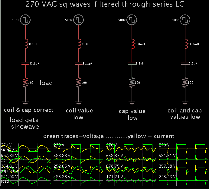
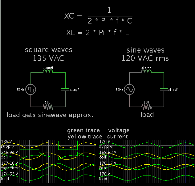
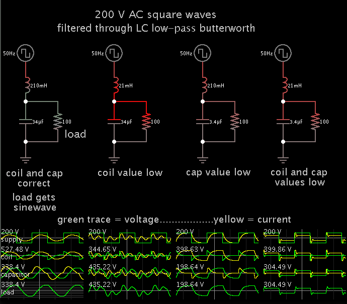
if any harmonics which has frequency equal to the resonant frequency, then XL =XC ,,so total reacance will be equal to 0, the only resistance that will left is the resistance of wire used in designing inductor , so it will short my output,,so to avoid this condition, I have put a 100W bulb in series with capacitor ,so that it can act as a damper.
since on attaching the filter ,my DC DC stage 's mosfets also blown it clearly means that there was a short circuit in my hbridge output stage, beacause i have checked my DC DC converter stage separetly with a load of 200w bulb and the circuit worked normal,,i have also checked my hbridge (without attaching filter) , it also worked normally,
one more thing if i apply a low voltage dc to input of hbridge + LC filter , i get a nice sine wave,,
so i think there is a problem in my filter design,
i have used 5MH INDUCTOR ,wound on ETD 39 (1mm gapped) ferrite core,
carier frequency is 16khz, cutoff is 5khz
and 0.22uf CAPACITOR (non polarized box type)
i am attaching some images of my inverter
this is my DC DC stage

this is my Hbridge

below is my LC filter

please anyone help me,, i think there is a problem in my filter design ,,either my core selection is not good or some other problem,,please guide me,,i am working on it since a large time,, and i have made my circuit 31 times again n again ,,but i got only failure,,,, i have checked my spwm waveform after Hbridge on DSO and it was as expected ,,so where is the problem..
I am working on microcontroller based sine wave inverter,
till now i have successfully designed my dc dc converter stage , i have also designed my h bridge circuit which is driven by microcontroller.
now the problem is as i connect my LC filter to the output of hbridge ,my hbridge mosfets as well as the mosfets that are used in DC DC converter stage gets damage.
if i don't attach the LC filter ,,and simply put a resistive load (100w bulb), bulb glows ,and circuit works normally.
if any harmonics which has frequency equal to the resonant frequency, then XL =XC ,,so total reacance will be equal to 0, the only resistance that will left is the resistance of wire used in designing inductor , so it will short my output,,so to avoid this condition, I have put a 100W bulb in series with capacitor ,so that it can act as a damper.
since on attaching the filter ,my DC DC stage 's mosfets also blown it clearly means that there was a short circuit in my hbridge output stage, beacause i have checked my DC DC converter stage separetly with a load of 200w bulb and the circuit worked normal,,i have also checked my hbridge (without attaching filter) , it also worked normally,
one more thing if i apply a low voltage dc to input of hbridge + LC filter , i get a nice sine wave,,
so i think there is a problem in my filter design,
i have used 5MH INDUCTOR ,wound on ETD 39 (1mm gapped) ferrite core,
carier frequency is 16khz, cutoff is 5khz
and 0.22uf CAPACITOR (non polarized box type)
i am attaching some images of my inverter
this is my DC DC stage
this is my Hbridge
below is my LC filter
please anyone help me,, i think there is a problem in my filter design ,,either my core selection is not good or some other problem,,please guide me,,i am working on it since a large time,, and i have made my circuit 31 times again n again ,,but i got only failure,,,, i have checked my spwm waveform after Hbridge on DSO and it was as expected ,,so where is the problem..