Continue to Site

Welcome to EDAboard.com

Welcome to our site! EDAboard.com is an international Electronics Discussion Forum focused on EDA software, circuits, schematics, books, theory, papers, asic, pld, 8051, DSP, Network, RF, Analog Design, PCB, Service Manuals... and a whole lot more! To participate you need to register. Registration is free. Click here to register now.

[SOLVED] Applying square wave to the transformer.

Status
Not open for further replies.

peeyushsigma

Member level 4
Joined
Apr 15, 2012
Messages
77
Helped
19
Reputation
38
Reaction score
17
Trophy points
1,288
Location
Bengaluru, Karnataka, India
Activity points
1,773
hello everyone,

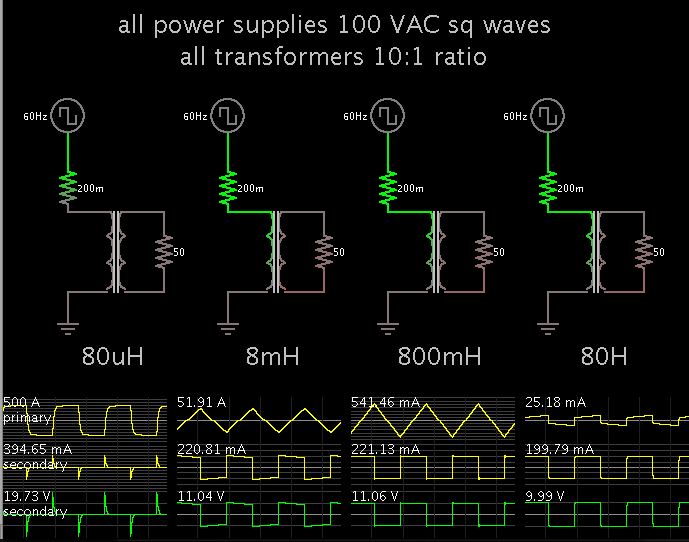
my question is what will be the output at the secondary of the transformer if we apply square wave at the primary side (suppose step down transformer of 10:1) of a transformer used in PSUs.

simulation in "NI-Multisim" shows the exact square wave with reduces amplitude by factor of 10...but i am not satisfied i was expecting impulses at the output.
 

Probably you simulated an ideal transformer that means all the frequencies will pass with the same attenuation.

The squarewave has many (infinite) harmonics; since real transformers have an inductive behaviour on both primary and secondary, also depending from source and load impedance, not all the frequency will pass with the same attenuation. This means the harmonic content of the secondary will be different from that of the primary, this will lead into a distorted output waveform. Pulses could also be present depending from edges of the signal and ciruital parameters.
 

It depends on the characteristics of the particular transformer. There are low frequency transformers and there are RF transformers.....
 

It depends on the characteristics of the particular transformer. There are low frequency transformers and there are RF transformers.....
thank u barry for quick reply,

you are right that there are low frequency and RF transformers ..but had restricted my question in low frequency transformer (50 to 60 Hz) which are used in ac to dc conversion in PSUs.

- - - Updated - - -

Dear albdg,

please explain me assuming the ideal transformer and the square wave frequency is 50 Hz....then what will be the observed output waveform ????
 

thank u barry for quick reply,

you are right that there are low frequency and RF transformers ..but had restricted my question in low frequency transformer (50 to 60 Hz) which are used in ac to dc conversion in PSUs.

As albbg implied, did you specify a "50 to 60 Hz" transformer model in you simulation, or did you just use an ideal model? Just because your question was low-frequency doesn't mean your model was.
 

lets not talk about simulations ...

please explain me assuming the ideal transformer and the square wave frequency is 50 Hz....then what will be the observed output waveform ????
 

I believe it was YOU who was talking about simulation: I quote: "simulation in "NI-Multisim" shows the exact square wave with reduces amplitude by factor of 10..."

An ideal transformer has no core losses, no impedance, and perfect coupling.

We've already established that your ideal transformer will couple a square-wave ideally.
 

the same of the input, attenuated by the transformer ratio
 

dear barry and albbg,

as far i know that transformer works on the principle of Faraday's law i.e. "Rate of change of flux linkage with respect to time is directly proportional to the induced EMF in a conductor or coil".. then square wave should produce impulses at discontinuities and no emf. where rate of change is zero.
 

an ideal transformer has infinite inductance (or some very high value in simulation). this is why it appears to be transferring dc. If you were to put a step function into your transformer and simulate a long period of time, you'd probably eventually see the output voltage start to drop.
 
From my experiments with simulations using Falstad's...

As to the Henry value of the primary, I find it can be within a wide range and you'll get square waves from the secondary.

Power transfer is more efficient when the primary has a larger Henry value.

As we reduce the primary's Henry value, the output starts to resemble spikes. Efficiency goes down.

These results can be observed in the simulations below.


Henry values of the primaries increase in steps of 100X.
 
Thanks BradtheRad, the simulation says what's expected. The flat top and bottom of the squarewave represent a DC value, while the edges represent AC values with harmonic content. Decreasing the inductance the lowpass effect is increased, then the DC (flat areas) is more and more attenuated while the edges are passing. Furthermore the derivative effect of the inductance becomes not negligible and the edges (spikes) increases in amplitude that should depends from the edge sharpness.

However you can use fft transform of your signal to see that no real DC signal is present in it (the flat are represent DC in the sense that no amplitude variation is present), unless the mean value is different from zero (not our case).
 
According to theory or by calculations,

the output voltage (or input side induced voltage is proportional to)is d Ip/dt
that is the change in input primary current (or flux)(and assuming core is mot saturated)........

By differentiating a square wave you will get a spike (delta) kind of wave form.......
for ramp => square wave..
for dc => nothing
for sine => cos (applying sine voltage will cause a cos current in a inductance(pure lagging load assumed))
 

Status
Not open for further replies.

Part and Inventory Search

Welcome to EDABoard.com

Sponsor

Back
Top