Continue to Site

Welcome to EDAboard.com

Welcome to our site! EDAboard.com is an international Electronics Discussion Forum focused on EDA software, circuits, schematics, books, theory, papers, asic, pld, 8051, DSP, Network, RF, Analog Design, PCB, Service Manuals... and a whole lot more! To participate you need to register. Registration is free. Click here to register now.

CMOS Self-Biased Cascode Power Amplifier

Status
Not open for further replies.

Osawa_Odessa

Banned
Joined
Dec 31, 2012
Messages
168
Helped
1
Reputation
2
Reaction score
1
Trophy points
1,298
Activity points
0
Hi,
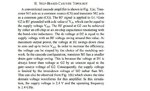
I am studying the article "A 2.4-GHz 0.18-um CMOS Self-Biased Cascode Power Amplifier" (attached). Here are what I am confused. Please help. Thank you.
95895d1378632779-class-i-pa-text-modified-.jpg

95896d1378632799-class-i-pa-modified-.jpg
 

Attachments

  • Class I PA text (modified).JPG
    Class I PA text (modified).JPG
    96.3 KB · Views: 129
  • Class I PA (modified).JPG
    Class I PA (modified).JPG
    75.8 KB · Views: 145
  • A 2.4-GHz 0.18-um CMOS Self-Biased.pdf
    467.6 KB · Views: 56

1-In order to give max. swing to M1, Vdd has been used.Otherwise Vds of M1 will be lower so consequently swing will also be low.
2-RF chokes are useless in RFIC circuits.Instead using a resistor will also supply wanted gate voltage.Because there is practically no DCcurrent flows.
3-Ls inductor is used to able to play around input impedance to get or approach to optimum impedance for lowest NF.
 
Thank you, BigBoss.
1-In order to give max. swing to M1, Vdd has been used.Otherwise Vds of M1 will be lower so consequently swing will also be low.
I see it now. Can I ask another question about choosing the bias voltage?
Here is a section in Design of Analog CMOS integrated circuits by Razavi. I am confused about how to determine the valid range for bias voltage.
Please help me with the question in the picture below.

95918d1378666184-cascode-13.jpg

95917d1378665412-cascode-12-modified-.jpg


2-RF chokes are useless in RFIC circuits.Instead using a resistor will also supply wanted gate voltage.Because there is practically no DC current flows.
Well, I have mistaken for a long time. Why RF choke can't be use in RFIC? Because its big size? I have seen a lot of RF power amplifier at uF technology use inductors to bias for transistor. Are these inductors RF chokes?
About using resistor:
+ In DC mode: There is no DC current => No losses.
+ In AC mode: RF signal (current) will flow through this resistor and causes losses. If so why resistor is used?
3-Ls inductor is used to able to play around input impedance to get or approach to optimum impedance for lowest NF.
I thought it is a parasitic parameter.:lol:
The use of this inductor will affect the operation of power amplifier in AC mode. I think we have a trade-off here, right?
 

Attachments

  • Cascode 12 (modified).JPG
    Cascode 12 (modified).JPG
    100.8 KB · Views: 90
  • Cascode 13.JPG
    Cascode 13.JPG
    61.5 KB · Views: 89
Last edited:

Vin is NOT AC signal level, Vin is Vgs1 so it's bias voltage.If we assume that the transistors are identical ( so it's true) Vgs1=Vgs2 for the same current.
Therefore there isn't any unknown variable in this calculation.Vout has some option to make these transistors both in saturation or one of them.So you should carefully select Vb so that Vout will satisfy the inequality in eq.1 (look at the explanation, he talks about a variable operating point that will cause a compromise )
2-RF Chokes can be used for discrete Linear Amplifiers/Power Amplifiers but not on the silicon because of their huge size.Instead, RF Chokes may be placed extrenally on off-chip.If you have sufficient space, you can of course use them but it won't be very practical.
3-Ls inductor will play a role to obtain optimum NF by compensating Cgs Cgd and the others.Because each Low Noise Transistor has intrinsically determined a Optimum Noise Impedance.Ls is for that..
 
Thank you, BigBoss.
Can you help me explain the sentence in the first picture?
In the cascode configuration, transistor M1 has a smaller drain–gate voltage swing. This is because the voltage at D1 is always lower than voltage at G2 by an amount equal to the gate–source voltage of G2.
I really can't figure out why!!!
 

Status
Not open for further replies.

Part and Inventory Search

Welcome to EDABoard.com

Sponsor

Back
Top