Continue to Site

Welcome to EDAboard.com

Welcome to our site! EDAboard.com is an international Electronics Discussion Forum focused on EDA software, circuits, schematics, books, theory, papers, asic, pld, 8051, DSP, Network, RF, Analog Design, PCB, Service Manuals... and a whole lot more! To participate you need to register. Registration is free. Click here to register now.

[SOLVED] Help with Latch IC 74LS373 based latching ciruit

Status
Not open for further replies.

sharikbaig

Member level 1
Joined
Aug 24, 2013
Messages
41
Helped
4
Reputation
8
Reaction score
4
Trophy points
1,288
Activity points
1,613
page1.jpgHi All,
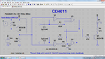
I have attached an image of the circuit diagram. The led in the circuit is always Off. It just turns on when i press SW1, but it again turns Off as soon as i release SW1. It doesnt latch in HIGH state. Can anyone please help me sort out the problem ?.:sad:
Datasheet of 74LS373 is also attached.View attachment sn74ls373rev5.pdf
Thanks in Advance !
 
Last edited:

'LS373 is a 'transparent' latch.

This means that while your Enable is active (and in your circuit it is always active - pin 11 high) then the data presented to an input will always immediately get reflected to the output. As long as output is enabled (which it is - pin 1 is Low)

For this latch to hold data, you must do the following :

1. Enable gates (pin 11 high)
2. Place data on input (pin 3) - i.e. sw1 is closed (hi) or open (low)
3. remove enable (pin 11 low)
4. release data on input pin 3 - now it won't matter what you do on pin 3, output will remain as it was just before step 3
 
Have a look at the truth table. You have LE fixed High, hence output equals input....
Need to either set LE low to latch the input or choose different latch.

Looking at your circuit explore the S-R latch or even two cross coupled NAND gates as possibilities or ideas.
 
'LS373 is a 'transparent' latch.

This means that while your Enable is active (and in your circuit it is always active - pin 11 high) then the data presented to an input will always immediately get reflected to the output. As long as output is enabled (which it is - pin 1 is Low)

For this latch to hold data, you must do the following :

1. Enable gates (pin 11 high)
2. Place data on input (pin 3) - i.e. sw1 is closed (hi) or open (low)
3. remove enable (pin 11 low)
4. release data on input pin 3 - now it won't matter what you do on pin 3, output will remain as it was just before step 3
Have a look at the truth table. You have LE fixed High, hence output equals input....
Need to either set LE low to latch the input or choose different latch.

Thanks for your reply, Guys,
What i am trying to do is, Turn on a led by pressing a momentary switch and then turn it off using other momentary switch.
A single momentary switch to turn ON/OFF is also acceptable.
Is there any other way to do this, some other ic or change in the existing circuit ?
 

Thanks Pinout,
Is there any IC available to do this.
 

A single D-FF (7474) configured as a Toggle flip flop (where Q/ is connected to D) will do what you need using a single switch. HOWEVER (!!) you need to make sure your switch is properly debounced, otherwise the results will be erratic
 
Something like the 74LS00 or 4011 will work (any 2 input NAND gate).

The beauty of this simple circuit is it actually debounces your switch, i.e. switch pressed takes input low and switches the state and output, any bouncing on that switch is ignored.
Similar for other switch input.
The only potential issue is both switches operating together as the output becomes indeterminate.
 
Thanks Everyone,
Posted a while ago & everyone helped amazingly, Thank you very much.
I ordered these IC's and will get by tomorrow, will try with these & update you.
Thanks again.
 

If you have CD4011, the remaining 2 gates can be used to combine the 2 switches in one. If you like I will draw the schematic for you.

Note: Since the output current of the CMOS series 4000 is relatively low, an NPN transistor should be added as a buffer to drive the LED.

If 74HC00 is used instead, there will be no need to add a buffer since its output can turn on the LED (about 5 mA).
 
Last edited:
If you have CD4011, the remaining 2 gates can be used to combine the 2 switches in one. If you like I will draw the schematic for you.

Note: Since the output current of the CMOS series 4000 is relatively low, a transistor should be added as a buffer to drive the LED.

I am feeling shameful to ask, but it will be a great pleasure if you draw it for me......:oops:
 

It is also my pleasure doing it ;)

About the circuit:
R1 & C1 and R2 & C2 are added to delay the feedback output and it helps in debouncing the switch.
R3 & C3 is added to let the output of U4 be high at power up. The initial state of the LED is off (U3 output is low).
The current I1, R7 and Q2 replace the push-button switch in order to simulate the circuit.
 

Attachments

  • RSflipflop-1SW_03.png
    RSflipflop-1SW_03.png
    105 KB · Views: 147
Last edited:
Thanks KerimF, you are so helpful.
btw its dusk here, in India. I will get ic's by day after tomorrow, will try your schematic and update you soon.
Thanks.
 

Hi KerimF,
I like that circuit, clever how the output levels are used to 'steer' the input from the switch to the appropriate SR latch.
Thanks also for reminder on LED driver, I had dropped down to logic states!
 
Thank you so much KerimF, will try this tomorrow after i get the IC.
You people are very helpful, Thanks.
 

Sorry guys, its festival time in India, So all the shops are closed here, I will get the IC's by Saturday & will update you then.
By the time, Actually i want to control 7 led's with 7 or 14 Pushbuttons, so is there any IC with more number of NAND gates ?
Any other idea is also welcomed.
Thanks.
 

Out of curiosity, why you don't like using simple 7 1P1T switches only?

Good Question!
Actually i saw these momentary switches at many applications, such as coffee maker, etc.
They are easy to use and safe from electrical hazards (as a relay is used to switch high power loads). As a Electronics Hobbyist i decided to study them and make them myself and use them to control appliances at my home. Just to make something different.
Thanks.

- - - Updated - - -

Hey i got CD4043 from somewhere in trash, and built the attached circuit. Its working well and the IC also has 4 latches. So 2 IC's will do my work. So the topic is SOLVED & Thank you very much everyone. This would not have been possible without your efforts.
Special thanks to KerimF.
Here is the Circuit Diagram:
ckt.jpg
Again, Thanks!:smile:
 

I actually made a similar project back in the 80's when experimemting with programmable logic (the good old days!) using PAL's and my favorite GAL's.

Each momentary switch would latch a solenoid valve (and when activated switch off the others valves), a bit like a manual washing machine. This single chip solution plus solenoid drivers worked very well....... except it introduced me to electrostatic discharge! When a user approached the panel to press the button it switched correctly BEFORE they pressed the button!!!! It could have been a useful touch switch (which weren't very common then), but I learnt how to filter out, clamp and provide immunity instead!

These small chips were 18 or 24 pins?, I must look them up again. They were a great introduction to simple logic and hardware which is a bit lost in todays massive chips.
 
Status
Not open for further replies.

Part and Inventory Search

Welcome to EDABoard.com

Sponsor

Back
Top