Continue to Site

Welcome to EDAboard.com

Welcome to our site! EDAboard.com is an international Electronics Discussion Forum focused on EDA software, circuits, schematics, books, theory, papers, asic, pld, 8051, DSP, Network, RF, Analog Design, PCB, Service Manuals... and a whole lot more! To participate you need to register. Registration is free. Click here to register now.

Generating Sine Wave using PWM of PIC16F877A??

Status
Not open for further replies.

xpress_embedo

Advanced Member level 4
Joined
Jul 5, 2011
Messages
1,154
Helped
161
Reputation
396
Reaction score
189
Trophy points
1,353
Location
India
Activity points
10,591
Hello!!!
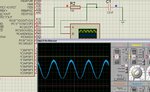
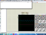
I am not able to generate Sine wave of frequency 200Hz when configured PWM Frequency of PIC16F877A to 10KHz and PIC is operating at 20MhZ Crystal.

This is MATLAB Code to generate table.

Code C - [expand]
1
2
3
4
5
6
7
8
9
10
11
12
fSampling = 10000;      %10Khz Sampling Rate
F = 200;                %200hz Frequency
t = 0:1/fSampling:1-1/fSampling;
 
xSignal = sin(2*pi*F*t);
% plot(t(1:100),xSignal(1:100));
 
xSignalPWM = xSignal(1:100);
xSignalPWM = xSignalPWM * 250;
xSignalPWM = xSignalPWM + 249.5067;
xSignalPWM = round(xSignalPWM);
plot(xSignalPWM);


Error.png
Have a look at my code attached below, please help.
View attachment PWM_Test.zip
 

In hitech there is math.h and

Code C - [expand]
1
2
3
4
5
6
value = 250 + (int)250*sin((float)i*314 * 2/10000);
    CCPR1L = value>>2;
    value = value & 0x03;
    CCP1CON = CCP1CON | (value<<4);
    if(++i > 99)
    i=0;


works nicely...
95282d1377348705-untitled.jpg


- - - Updated - - -

And also you have made trouble with i value It goes more than 99 to access the array table..
 

Attachments

  • untitled.JPG
    untitled.JPG
    89.3 KB · Views: 368
First of all thanks for your reply

Now I am operating my PIC at 20MHz and my PWM Frequency is 10KHz means i have to pass 10000 samples per second.

Means Single Sample in 1/10000 sec
Means 1 Sample in 100usec

And with your code to calculate the sine wave i am getting a frequency which is not in HZ

Very_Slow.JPG

Correct me if i am wrong


Even correcting the value to 99 in my table method still it is not working.

Please help me, if your table code is working then attached it here.
In my code i had used and timer interrupt of 100usec to pass table values to change duty cycle.

- - - Updated - - -

I changed my code as follow:-


Code C - [expand]
1
2
3
4
5
6
7
8
9
10
11
12
13
14
15
16
17
18
19
20
21
22
23
24
25
26
27
28
29
30
31
32
33
34
35
36
37
38
39
40
41
42
43
44
45
46
47
48
49
50
51
52
53
54
55
56
57
58
59
60
61
62
63
64
65
66
67
68
69
70
71
72
73
74
75
76
77
78
79
80
81
82
83
84
85
86
87
88
89
90
#include <htc.h>
#include <math.h>
#define _XTAL_FREQ  20000000UL
 
__CONFIG(FOSC_HS & WDTE_OFF & LVP_OFF);
 
void PWM_Init(float frequency,unsigned char timer_prescalar);
void PWM_Set_Duty(unsigned char duty_cycle,unsigned char timer_presclar);
void PWM_Stop();
 
const unsigned int table[100] = 
{250 , 281 , 312 , 342 , 370 , 396 , 421 , 442 , 461 , 476 , 487 , 495 , 499 , 499 , 495 , 487 ,
476 , 461 , 442 , 421 , 396 , 370 , 342 , 312 , 281 , 250 , 218 , 187 , 157 , 129 , 103 , 78 ,
57 , 38 , 23 , 12 , 4 , 0 , 0 , 4 , 12 , 23 , 38 , 57 , 78 , 103 , 129 , 157 , 187 , 218 , 250 ,
281 , 312 , 342 , 370 , 396 , 421 , 442 , 461 , 476 , 487 , 495 , 499 , 499 , 495 , 487 , 476 ,
461 , 442 , 421 , 396 , 370 , 342 , 312 , 281 , 250 , 218 , 187 , 157 , 129 , 103 , 78 , 57 ,
38 , 23 , 12 , 4 , 0 , 0 , 4 , 12 , 23 , 38 , 57 , 78 , 103 , 129 , 157 , 187 , 218};
 
unsigned char i=0;
unsigned char flag = 0;
unsigned int value;
 
void interrupt Timer_ISR(void)
{
    TMR1H = 0xFE;
    TMR1L = 0x09;
    i++;
    flag = 1;
    TMR1IF = 0;
}
 
void main()
{
    TRISC2 = 0;
    T2CON = 0b00000101;
    PWM_Init(10000,4);
    T1CON = 0x01;
    TMR1IF = 0;
    TMR1H = 0xFE;
    TMR1L = 0x09;
    TMR1IE = 1;
    INTCON = 0xC0;
    while(1)
    {    
        if(flag == 1)
        {           
            if(i>=99)
                i=0;
            value = table[i];
            CCPR1L = (value>>2);
            value = value & 0x03;
            CCP1CON = CCP1CON | (value<<4);         
            flag = 0;
        }       
    }
}
 
void PWM_Init(float frequency,unsigned char timer_prescalar)
{
    float temp;
    TRISC2 = 0;
    /*
    PR2 = (FOSC/(4*PWMFreq*TMR2 Prescalar)-1)
    */
    temp = _XTAL_FREQ/frequency;
    temp = temp/4;
    temp = temp/timer_prescalar;
    PR2 = (unsigned char)(temp);
    PR2 = PR2-1;
    CCPR1L = 0x00;
    CCP1CON = 0x0C; //Set Zero Percent Duty Cycle Initially
}
void PWM_Set_Duty(unsigned char duty_cycle,unsigned char timer_prescalar)
{
    unsigned int register_value;
    float frequency;
    
    frequency = (_XTAL_FREQ/4);
    frequency = (frequency/timer_prescalar);
    frequency = (frequency/(PR2+1));    //Frequency of PWM Signal
    
    frequency = (frequency*100)/(duty_cycle);
    
    register_value = (_XTAL_FREQ)/(unsigned int)frequency;
    register_value = (register_value/timer_prescalar);
 
    CCPR1L = (register_value>>2);
    register_value = register_value & 0x03;
    CCP1CON = CCP1CON | (register_value<<4);
}


Error.png

But still there is some sort of deformity, and What is the logic of that low pass filter 10K with 100nf Capacitor.

i used this link to calculate cut-off frequency.
http://sim.okawa-denshi.jp/en/PWMtool.php

My Frequency is 159Hz as i am generating signal of 200Hz, it must be cut-down.
Please explain me the meaning of the filter we had added to convert pwm signal to sine wave.
 

Attachments

  • Error.png
    Error.png
    268.8 KB · Views: 129

I am not getting the idea of designing the simple low pass filter RC Filter.

When values is 10k and 100nf, i am getting this waveform as follow on the oscilloscope.

SQUARE WAVE

Square_Wave_Error.png

Then i changed the value of resistor to 160 ohm to generate cut-off frequency of 10Khz as my pwm frequency is 10Khz
Hence my Square Waveform is as follow:-

Square_Wave_Error.png

But my sawtooth and sine wave gets distorted with these value of resistor and capacitor, while they are working fine when R=10K and C=100nF

SINE WAVE
Square_Wave_Error.png


SAWTOOTH WAVEFORM
Square_Wave_Error.png

- - - Updated - - -


Code C - [expand]
1
2
3
4
5
6
7
8
9
10
11
12
13
14
15
16
17
18
19
20
21
22
23
24
25
26
27
28
29
30
31
32
33
34
35
36
37
38
39
40
41
42
43
44
45
46
47
48
49
50
51
52
53
54
55
56
57
58
59
60
61
62
63
64
65
66
67
68
69
70
71
72
73
74
75
76
77
78
79
80
81
82
83
84
85
86
87
88
89
90
91
92
93
94
95
96
97
98
99
100
101
102
103
104
105
106
107
108
109
110
111
112
113
114
115
116
#include <htc.h>
#define _XTAL_FREQ  20000000UL
 
__CONFIG(FOSC_HS & WDTE_OFF & LVP_OFF);
 
void PWM_Init(float frequency,unsigned char timer_prescalar);
void PWM_Set_Duty(unsigned char duty_cycle,unsigned char timer_presclar);
void PWM_Stop();
 
//#define SINE_WAVE
#define SAWTOOTH_WAVE
//#define SQUARE_WAVE
 
#if defined(SINE_WAVE)
const unsigned int table[100] = 
{250 , 281 , 312 , 342 , 370 , 396 , 421 , 442 , 461 , 476 , 487 , 495 , 499 , 499 , 495 , 487 ,
476 , 461 , 442 , 421 , 396 , 370 , 342 , 312 , 281 , 250 , 218 , 187 , 157 , 129 , 103 , 78 ,
57 , 38 , 23 , 12 , 4 , 0 , 0 , 4 , 12 , 23 , 38 , 57 , 78 , 103 , 129 , 157 , 187 , 218 , 250 ,
281 , 312 , 342 , 370 , 396 , 421 , 442 , 461 , 476 , 487 , 495 , 499 , 499 , 495 , 487 , 476 ,
461 , 442 , 421 , 396 , 370 , 342 , 312 , 281 , 250 , 218 , 187 , 157 , 129 , 103 , 78 , 57 ,
38 , 23 , 12 , 4 , 0 , 0 , 4 , 12 , 23 , 38 , 57 , 78 , 103 , 129 , 157 , 187 , 218
};
 
#elif defined(SAWTOOTH_WAVE)
const unsigned int table[100] = 
{0 , 10 , 20 , 30 , 40 , 50 , 60 , 70 , 80 , 90 , 100 , 110 , 120 , 130 , 140 , 150 , 160 , 170 ,
180 , 190 , 200 , 210 , 220 , 230 , 240 , 250 , 260 , 270 , 280 , 290 , 300 , 310 , 320 , 330 ,
340 , 350 , 360 , 370 , 380 , 390 , 400 , 410 , 420 , 430 , 440 , 450 , 460 , 470 , 480 , 490 ,
0 , 10 , 20 , 30 , 40 , 50 , 60 , 70 , 80 , 90 , 100 , 110 , 120 , 130 , 140 , 150 , 160 , 170 ,
180 , 190 , 200 , 210 , 220 , 230 , 240 , 250 , 260 , 270 , 280 , 290 , 300 , 310 , 320 , 330 ,
340 , 350 , 360 , 370 , 380 , 390 , 400 , 410 , 420 , 430 , 440 , 450 , 460 , 470 , 480 , 490
};
 
#elif defined(SQUARE_WAVE)
const unsigned int table[100] = 
{500 , 500 , 500 , 500 , 500 , 500 , 500 , 500 , 500 , 500 , 500 , 500 , 500 , 500 , 500 , 500 ,
500 , 500 , 500 , 500 , 500 , 500 , 500 , 500 , 500 , 0 , 0 , 0 , 0 , 0 , 0 , 0 , 0 , 0 , 0 , 0 ,
0 , 0 , 0 , 0 , 0 , 0 , 0 , 0 , 0 , 0 , 0 , 0 , 0 , 0 , 500 , 500 , 500 , 500 , 500 , 500 , 500 ,
500 , 500 , 500 , 500 , 500 , 500 , 500 , 500 , 500 , 500 , 500 , 500 , 500 , 500 , 500 , 500 ,
500 , 500 , 0 , 0 , 0 , 0 , 0 , 0 , 0 , 0 , 0 , 0 , 0 , 0 , 0 , 0 , 0 , 0 , 0 , 0 , 0 , 0 , 0 ,
0 , 0 , 0 , 0
};
#endif
 
unsigned char i=0;
unsigned char flag = 0;
unsigned int value;
 
void interrupt Timer_ISR(void)
{
    TMR1H = 0xFE;
    TMR1L = 0x09;
    i++;
    flag = 1;
    TMR1IF = 0;
}
 
void main()
{
    TRISC2 = 0;
    T2CON = 0b00000101;
    PWM_Init(10000,4);
    T1CON = 0x01;
    TMR1IF = 0;
    TMR1H = 0xFE;
    TMR1L = 0x09;
    TMR1IE = 1;
    INTCON = 0xC0;
    while(1)
    {    
        if(flag == 1)
        {           
            if(i>=99)
                i=0;
            value = table[i];
            CCPR1L = (value>>2);
            value = value & 0x03;
            CCP1CON = CCP1CON | (value<<4);         
            flag = 0;
        }       
    }
}
 
void PWM_Init(float frequency,unsigned char timer_prescalar)
{
    float temp;
    TRISC2 = 0;
    /*
    PR2 = (FOSC/(4*PWMFreq*TMR2 Prescalar)-1)
    */
    temp = _XTAL_FREQ/frequency;
    temp = temp/4;
    temp = temp/timer_prescalar;
    PR2 = (unsigned char)(temp);
    PR2 = PR2-1;
    CCPR1L = 0x00;
    CCP1CON = 0x0C; //Set Zero Percent Duty Cycle Initially
}
void PWM_Set_Duty(unsigned char duty_cycle,unsigned char timer_prescalar)
{
    unsigned int register_value;
    float frequency;
    
    frequency = (_XTAL_FREQ/4);
    frequency = (frequency/timer_prescalar);
    frequency = (frequency/(PR2+1));    //Frequency of PWM Signal
    
    frequency = (frequency*100)/(duty_cycle);
    
    register_value = (_XTAL_FREQ)/(unsigned int)frequency;
    register_value = (register_value/timer_prescalar);
 
    CCPR1L = (register_value>>2);
    register_value = register_value & 0x03;
    CCP1CON = CCP1CON | (register_value<<4);
}


The glitches in your sine wave output is due to loading the pwm dutycycle in improper positions (It misses a pulse)..
Here I am attaching my project file which gives more stable output...
View attachment My sine.7z

And about your filter design problem, the cutoff frequency you are finding are only valid for sine wave.. and for remaining waveforms They are changed because of maximum rate of change... for a highly changing waveform the RC constant must be very low and for a slow waveform it can be high as to get the smooth waveform....

Your above i value problem may cause total program to corrupt if you didnt concentrate on it.....
and also you need not construct table for every your waveform, i * 5 in enough for Ramp and you don need any PWM for square wave...
Ask if any further problems....

Regards,
Venkadesh M.
 
Last edited:

Code:
#include <htc.h>
#define _XTAL_FREQ  20000000UL
 
__CONFIG(FOSC_HS & WDTE_OFF & LVP_OFF);
 
void PWM_Init(float frequency,unsigned char timer_prescalar);
void PWM_Set_Duty(unsigned char duty_cycle,unsigned char timer_presclar);
void PWM_Stop();
 
#define SINE_WAVE
//#define SAWTOOTH_WAVE
//#define SQUARE_WAVE
 
#if defined(SINE_WAVE)
const unsigned int table[100] = 
{250 , 281 , 312 , 342 , 370 , 396 , 421 , 442 , 461 , 476 , 487 , 495 , 499 , 499 , 495 , 487 ,
476 , 461 , 442 , 421 , 396 , 370 , 342 , 312 , 281 , 250 , 218 , 187 , 157 , 129 , 103 , 78 ,
57 , 38 , 23 , 12 , 4 , 0 , 0 , 4 , 12 , 23 , 38 , 57 , 78 , 103 , 129 , 157 , 187 , 218 , 250 ,
281 , 312 , 342 , 370 , 396 , 421 , 442 , 461 , 476 , 487 , 495 , 499 , 499 , 495 , 487 , 476 ,
461 , 442 , 421 , 396 , 370 , 342 , 312 , 281 , 250 , 218 , 187 , 157 , 129 , 103 , 78 , 57 ,
38 , 23 , 12 , 4 , 0 , 0 , 4 , 12 , 23 , 38 , 57 , 78 , 103 , 129 , 157 , 187 , 218
};
 
#elif defined(SAWTOOTH_WAVE)
const unsigned int table[100] = 
{0 , 10 , 20 , 30 , 40 , 50 , 60 , 70 , 80 , 90 , 100 , 110 , 120 , 130 , 140 , 150 , 160 , 170 ,
180 , 190 , 200 , 210 , 220 , 230 , 240 , 250 , 260 , 270 , 280 , 290 , 300 , 310 , 320 , 330 ,
340 , 350 , 360 , 370 , 380 , 390 , 400 , 410 , 420 , 430 , 440 , 450 , 460 , 470 , 480 , 490 ,
0 , 10 , 20 , 30 , 40 , 50 , 60 , 70 , 80 , 90 , 100 , 110 , 120 , 130 , 140 , 150 , 160 , 170 ,
180 , 190 , 200 , 210 , 220 , 230 , 240 , 250 , 260 , 270 , 280 , 290 , 300 , 310 , 320 , 330 ,
340 , 350 , 360 , 370 , 380 , 390 , 400 , 410 , 420 , 430 , 440 , 450 , 460 , 470 , 480 , 490
};
 
#elif defined(SQUARE_WAVE)
const unsigned int table[100] = 
{500 , 500 , 500 , 500 , 500 , 500 , 500 , 500 , 500 , 500 , 500 , 500 , 500 , 500 , 500 , 500 ,
500 , 500 , 500 , 500 , 500 , 500 , 500 , 500 , 500 , 0 , 0 , 0 , 0 , 0 , 0 , 0 , 0 , 0 , 0 , 0 ,
0 , 0 , 0 , 0 , 0 , 0 , 0 , 0 , 0 , 0 , 0 , 0 , 0 , 0 , 500 , 500 , 500 , 500 , 500 , 500 , 500 ,
500 , 500 , 500 , 500 , 500 , 500 , 500 , 500 , 500 , 500 , 500 , 500 , 500 , 500 , 500 , 500 ,
500 , 500 , 0 , 0 , 0 , 0 , 0 , 0 , 0 , 0 , 0 , 0 , 0 , 0 , 0 , 0 , 0 , 0 , 0 , 0 , 0 , 0 , 0 ,
0 , 0 , 0 , 0
};
#endif
 
unsigned char i=0;
unsigned char flag = 0;
unsigned int value;
 
void interrupt Timer_ISR(void)
{
	TMR1IF = 0;
	value = table[i];
    CCPR1L = (value>>2);
    value = value & 0x03;
	CCP1CON = CCP1CON | (value<<4);
    if(++i > 99)
   		i=0;     
    TMR1H = 0xFE;
    TMR1L = 0x09;
}
 
void main()
{
    TRISC2 = 0;
    T2CON = 0b00000101;
    PWM_Init(10000,4);
    T1CON = 0x01;
    TMR1IF = 0;
    TMR1H = 0xFE;
    TMR1L = 0x09;
    TMR1IE = 1;
    INTCON = 0xC0;
    while(1)
    {
    }
}
 
void PWM_Init(float frequency,unsigned char timer_prescalar)
{
    float temp;
    TRISC2 = 0;
    /*
    PR2 = (FOSC/(4*PWMFreq*TMR2 Prescalar)-1)
    */
    temp = _XTAL_FREQ/frequency;
    temp = temp/4;
    temp = temp/timer_prescalar;
    PR2 = (unsigned char)(temp);
    PR2 = PR2-1;
    CCPR1L = 0x00;
    CCP1CON = 0x0C; //Set Zero Percent Duty Cycle Initially
}
void PWM_Set_Duty(unsigned char duty_cycle,unsigned char timer_prescalar)
{
    unsigned int register_value;
    float frequency;
    
    frequency = (_XTAL_FREQ/4);
    frequency = (frequency/timer_prescalar);
    frequency = (frequency/(PR2+1));    //Frequency of PWM Signal
    
    frequency = (frequency*100)/(duty_cycle);
    
    register_value = (_XTAL_FREQ)/(unsigned int)frequency;
    register_value = (register_value/timer_prescalar);
 
    CCPR1L = (register_value>>2);
    register_value = register_value & 0x03;
    CCP1CON = CCP1CON | (register_value<<4);
}

I am getting distorted wave.
I saw your code, my code is almost like that.
I dont know which ide you used for your project.
So i only saw you code but not able to compiler it.
I used Hitech C compiler put _XTAL_FREQ definition in my code and you can run it in any IDE with hitech tool suite...

- - - Updated - - -

One think to have in mind, you can change the output waveform frequency by timer values only not by PWM values....
 

I am not getting any wave with your code when compiled, dont know why??
Have to debug it.

One think to have in mind, you can change the output waveform frequency by timer values only not by PWM values....

I didn't get the meaning of this line.
 

you are calculating the value of PR2 using frequency... but Its just for resolution of PWM and if you put it less than dutycycle value the program wont work...

you have to calculate and load the timer values acccording to the output frequency...

Got it?
 

how can generate three phase sinewave by using pic16f877a
 

Status
Not open for further replies.

Similar threads

Part and Inventory Search

Welcome to EDABoard.com

Sponsor

Back
Top