Continue to Site

Welcome to EDAboard.com

Welcome to our site! EDAboard.com is an international Electronics Discussion Forum focused on EDA software, circuits, schematics, books, theory, papers, asic, pld, 8051, DSP, Network, RF, Analog Design, PCB, Service Manuals... and a whole lot more! To participate you need to register. Registration is free. Click here to register now.

ADC value conversion with PIC16F876A and seven segment multiplexing

Status
Not open for further replies.

john120

Banned
Joined
Aug 13, 2011
Messages
257
Helped
11
Reputation
22
Reaction score
10
Trophy points
1,298
Activity points
0
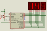
Hello there,I am design a digital voltmeter 0-30V I am using PIC16F876A and ccs c for coding but I am having great problem with the conversion of adc value read to be converted into decimal for displaying on seven segment .

Please see the codes and let me know what I can change.

I am always reading 0s in the 3 seven segment display.
see the code here;please help.
PHP:
#include "16f876a.h"
#DEVICE ADC=10
#fuses HS,NOWDT
#use delay(clock=12000000)
#include<stdio.h>
#include<STDLIB.H>
#use standard_io(A)
#use standard_io(B)
#DEFINE PORTB
#DEFINE PORTC
#DEFINE PORTA
 

byte const digit[]={0xC0,0xF9,0xA4,0xB0,0x99,0x92,0x82,0xF8,0x80,0x90};

 char display[3];
int value;
unsigned long value1;
unsigned int value2; 
 
void main()
{
set_tris_a(0xff);
set_tris_b(0x00);
set_tris_c(0x00);  
output_b(0xff);
output_c(0xff);
setup_comparator(NC_NC_NC_NC);
   setup_adc(ADC_CLOCK_INTERNAL);
   setup_adc_ports(AN0);
   set_adc_channel(0);
   setup_vref(FALSE);   
     
 
   while(TRUE)
{

    delay_us(100);
    read_adc(ADC_read_only);  
    delay_us(100);    
    value=read_adc(ADC_read_only);

   value1=(value*5*6)/1023;
	value2=value1;


     delay_ms(5);
    output_low(PIN_b2);
     display[0]=(value2%10);       
     
     output_high(PIN_b4);  
	output_high(PIN_b5);    
     output_c(digit[display[0]]);
     
     delay_ms(5); 
output_low(PIN_b4); 
   	display[1]=(value2%10) ;        
    
	output_high(PIN_B5);  
    output_high(PIN_b2);
    output_c(digit[display[1]]);          
    delay_ms(5);
 
   delay_ms(5); 
output_low(PIN_b5); 
   	display[2]=(value2%100) ;        
    
	output_high(PIN_B2);  
    output_high(PIN_b2);
    output_c(digit[display[2]]);          
    delay_ms(5);

}
}
 

I'm not really a C programmer, but here's a few comments anyway:

I'm assuming b2, b4, and b5 are active-low digit enables, right?

I would do this a little differently. First, I would have all the enables inactive before I write data to portc, so that the data is already there when you enable the digit. The way you're doing it you have data from the previous digit enabled on both the old and the present digit at the same time-maybe this is causing the display to "appear" to have all zeroes.

Have you verified that the proper data is being written to portc? I'm not sure about the "output_c(digit(display[]))" statements; with all of C's typing constraints, maybe there's something wrong there (See, I told you I wasn't a C expert).
 

hi John120,
may be you wrong statement :
#DEFINE PORTB
#DEFINE PORTC
#DEFINE PORTA
can you share this?
 

Post your Circuit or mention how your SSDs are connected to PIC. All I can understand is PORTC is connected to a,b,c,d,e,f,g,dp of SSDs (Multiplexed). Which pins of PORTB is driving the SSDs?

ADC is not working. Maybe a bug of CCS C or Proteus. Change Analog Channel used and see if that works.


Code C - [expand]
1
2
3
4
5
6
7
8
9
10
11
12
13
14
15
16
17
18
19
20
21
22
23
24
25
26
27
28
29
30
31
32
33
34
35
36
37
38
39
40
41
42
43
44
45
46
47
48
49
50
51
52
53
54
55
56
57
58
#include <16F876A.h>
 
#device ADC=10
 
#FUSES NOWDT                    //No Watch Dog Timer
#FUSES NOBROWNOUT               //No brownout reset
#FUSES NOLVP                    //No low voltage prgming, B3(PIC16) or B5(PIC18) used for I/O
#FUSES HS 
 
#use delay(crystal=12MHz)
#use FIXED_IO( B_outputs=PIN_B7,PIN_B6,PIN_B5,PIN_B4,PIN_B3,PIN_B2,PIN_B1,PIN_B0 )
#use FIXED_IO( C_outputs=PIN_C7,PIN_C6,PIN_C5,PIN_C4,PIN_C3,PIN_C2,PIN_C1,PIN_C0 )
 
byte const digit[] = {0xC0,0xF9,0xA4,0xB0,0x99,0x92,0x82,0xF8,0x80,0x90}; 
unsigned char display[3]; 
int value;  
 
void main()
{
   setup_comparator(NC_NC_NC_NC); 
   setup_adc_ports(AN0);
   setup_adc(ADC_CLOCK_DIV_32);
   set_adc_channel(0);
     
   while(TRUE)
   {
      //TODO: User Code
      value = read_adc();
      value = (value * 5 * 6) / 1023; 
      //value = 123;
                 
      display[0] = (value % 10);
      display[1] = (value / 10) % 10;
      display[2] = (value / 100) ;  
      
      output_low(PIN_b2);   
      output_low(PIN_b4);
      output_low(PIN_b5); 
      output_c(digit[display[0]]);
      output_high(PIN_b2);
      delay_ms(2);
      
      output_low(PIN_b2);   
      output_low(PIN_b4);
      output_low(PIN_b5); 
      output_c(digit[display[1]]);
      output_high(PIN_b4);
      delay_ms(2);
      
      output_low(PIN_b2);   
      output_low(PIN_b4);
      output_low(PIN_b5); 
      output_c(digit[display[2]]);
      output_high(PIN_b5);
      delay_ms(2);    
   }
 
}

 
Last edited:

Hello,jayanth.devarayanadurga;I am running the codes you proposed but the values I am getting are not true.
For example when I input 13.8v I get on the SSDs 29.0V;4.7V the SSDs shows 19.5 and so on.......

see the codes here
PHP:
#include "16f876a.h"
#DEVICE ADC=10
#fuses HS,NOWDT
#use delay(clock=12000000)
#include<stdio.h>
#include<STDLIB.H>
#use standard_io(A)
#use standard_io(B)


byte const digit[]={0xC0,0xF9,0xA4,0xB0,0x99,0x92,0x82,0xF8,0x80,0x90};
char display[3];
int value;
unsigned long value1;
unsigned int value2; 
 
void main()
{
set_tris_a(0xff);
set_tris_b(0x00);
set_tris_c(0x00);  
output_b(0xff);
output_c(0xff);
   setup_comparator(NC_NC_NC_NC);   
   setup_adc_ports(AN0);
   setup_adc(ADC_CLOCK_DIV_32);
   set_adc_channel(0);
   setup_vref(FALSE);        
 
   while(TRUE)
{

    delay_us(100); 
    read_adc(ADC_START_only);
     delay_us(100);         
    value=read_adc(ADC_read_only);
     
   value1=(value*5*6)/1023;
	value2=value1;    
   
      display[0] = (value % 10);
      display[1] = (value / 10) % 10;
      display[2] = (value / 100) ; 


     delay_ms(2);
     output_low(PIN_b0);        
     output_high(PIN_b1);  
	 output_high(PIN_b2); 
      output_low(PIN_C7);   
     output_c(digit[display[0]]);
     
     delay_ms(2); 

    output_low(PIN_b1); 	        
	output_high(PIN_b0);  
    output_high(PIN_b2);
	output_low(PIN_C7);
    output_c(digit[display[1]]); 
      
    delay_ms(2); 

    
    output_low(PIN_b2);        
    output_high(PIN_b0);  
    output_high(PIN_b1);
	output_low(PIN_C7);
    output_c(digit[display[2]]);          
    delay_ms(2);

}
}
see SSDs pins connections below also you find the proteus simulation schematic:
a:c0
b:c1
c:c2
d:c3
e:c4
f:c5
g:c6

the PNP transistors BC327 has their pins on b0,b1 and b2 respectively
the analog input is on AN0 the Quartz I am using is 12MHZ.

Can you tel me where I have to connect the dot point for displaying float numbers like 22.5V


Please help.

Thanks
 

Attachments

  • DVM.zip
    74.6 KB · Views: 106
Last edited:

In you ISIS file you are not using SSD with DP (Decimal Point). Use SSD with DP. Here is the new code. I am simulating in Proteus but ADC is not working. Post the code in which ADC works. RC7 connects to DP.


Edit: Working project attached. I don't use CCS C much. Show me how to setup Timer1 to generate 200 us interrupts. I will provide a better code for SSD.


Code C - [expand]
1
2
3
4
5
6
7
8
9
10
11
12
13
14
15
16
17
18
19
20
21
22
23
24
25
26
27
28
29
30
31
32
33
34
35
36
37
38
39
40
41
42
43
44
45
46
47
48
49
50
51
52
53
54
55
56
57
58
59
60
61
62
63
64
65
66
67
68
69
70
71
72
73
74
75
76
77
78
79
80
81
82
83
84
85
86
87
88
89
90
91
92
93
94
95
96
#include <16F876A.h>
 
#device ADC=10
 
#FUSES NOWDT                    //No Watch Dog Timer
#FUSES NOBROWNOUT               //No brownout reset
#FUSES NOLVP                    //No low voltage prgming, B3(PIC16) or B5(PIC18) used for I/O
#FUSES HS 
 
#use delay(crystal=12MHz)
#use FIXED_IO( B_outputs=PIN_B7,PIN_B6,PIN_B5,PIN_B4,PIN_B3,PIN_B2,PIN_B1,PIN_B0 )
#use FIXED_IO( C_outputs=PIN_C7,PIN_C6,PIN_C5,PIN_C4,PIN_C3,PIN_C2,PIN_C1,PIN_C0 )
 
unsigned char CA[] = {0xC0, 0xF9, 0xA4, 0xB0, 0x99, 0x92, 0x82, 0xF8, 0x80, 0x90};
unsigned char CAdp[] = {0x40, 0x79, 0x24, 0x30, 0x19, 0x12, 0x02, 0x78, 0x00, 0x10};
unsigned char display[3], SSDVAL1 = 0, SSDVAL2 = 0, SSDVAL3 = 0;
float value;
unsigned int dummy = 0;
 
void turnoffssd(){
      output_low(PIN_b0);   
      output_low(PIN_b1);
      output_low(PIN_b2);   
}
 
void splitnum(){
      display[0] = (dummy % 10);
      display[1] = (dummy / 10) % 10;
      display[2] = (dummy / 100);
}
 
void main()
{
   set_tris_a(0xFF);
   set_tris_b(0x00);
   set_tris_c(0x00);
   output_b(0x00); 
   output_c(0x00);
   setup_comparator(NC_NC_NC_NC);    
   setup_adc_ports(AN0); 
   setup_adc(ADC_CLOCK_DIV_32); 
   set_adc_channel(0); 
   setup_vref(FALSE);
     
   while(TRUE)
   {
      //TODO: User Code
      delay_us(100);  
      read_adc(ADC_START_only); 
      delay_us(100);          
      value = read_adc(ADC_read_only);
      value = (value * 5.0 * 6.0) / 1023.0;
      value = 1.23;
      //value = 12.3;
      //value = 123.0;
      
      if((value >= 0.0) && (value < 10.0)){
                 dummy = (int)(value * 100);                  //1.23 becomes 123
                 splitnum();
                 SSDVAL1 = CA[display[0]];
                 SSDVAL2 = CA[display[1]];
                 SSDVAL3 = CAdp[display[2]];                 
      }
      else if((value >= 10.0) && (value < 100.0)){
                 dummy = (int)(value * 10);                   //12.3 becomes 123
                 splitnum();
                 SSDVAL1 = CA[display[0]];
                 SSDVAL2 = CAdp[display[1]];
                 SSDVAL3 = CA[display[2]];
      }
      else if((value >= 100.0) && (value < 1000.0)){
                 dummy = (int)value;
                 splitnum();
                 SSDVAL1 = CA[display[0]];
                 SSDVAL2 = CA[display[1]];
                 SSDVAL3 = CA[display[2]];
      } 
            
      turnoffssd();
       
      output_c(SSDVAL3);
      output_high(PIN_b0);
      delay_ms(2);
      
      turnoffssd();
      output_c(SSDVAL2);
      output_high(PIN_b1);
      delay_ms(2);
      
      turnoffssd(); 
      output_c(SSDVAL1);
      output_high(PIN_b2);
      delay_ms(2);    
   }
 
}


Attachments

  • CCS C SSD.rar
    41.6 KB · Views: 109
Last edited:

Fixed the code. Here is a version which uses Timer1 interrupt to display SSD data.

95320d1377451657-ssd.png


CCS C 5.x Code


Code C - [expand]
1
2
3
4
5
6
7
8
9
10
11
12
13
14
15
16
17
18
19
20
21
22
23
24
25
26
27
28
29
30
31
32
33
34
35
36
37
38
39
40
41
42
43
44
45
46
47
48
49
50
51
52
53
54
55
56
57
58
59
60
61
62
63
64
65
66
67
68
69
70
71
72
73
74
75
76
77
78
79
80
81
82
83
84
85
86
87
88
89
90
91
92
93
94
95
96
97
98
99
100
101
102
103
104
105
106
107
108
109
110
111
112
113
114
115
116
117
118
119
120
121
122
123
124
125
126
127
128
129
130
131
132
133
134
135
136
137
138
139
140
141
142
143
144
145
#include <16F876A.h>
 
//ADC resolution
#device ADC=10
//CONFIG words
#FUSES NOWDT                    //No Watch Dog Timer
#FUSES NOBROWNOUT               //No brownout reset
#FUSES NOLVP                    //No low voltage prgming, B3(PIC16) or B5(PIC18) used for I/O
#FUSES HS 
 
//Clock used for delay routines
#use delay(crystal=12MHz)
 
#use FIXED_IO(B_outputs=PIN_B7,PIN_B6,PIN_B5,PIN_B4,PIN_B3,PIN_B2,PIN_B1,PIN_B0)
#use FIXED_IO(C_outputs=PIN_C7,PIN_C6,PIN_C5,PIN_C4,PIN_C3,PIN_C2,PIN_C1,PIN_C0)
 
//Global Variables
unsigned int8 enablessdx = 0;
unsigned char display[3], SSDVAL1 = 0, SSDVAL2 = 0, SSDVAL3 = 0;
unsigned long dummy = 0;
//Function Definitions
 
void turnoffssd(){
      output_low(PIN_b0);   
      output_low(PIN_b1);
      output_low(PIN_b2);   
}
 
void splitnum(){
      display[0] = (dummy % 10);
      display[1] = (dummy / 10) % 10;
      display[2] = (dummy / 100);
}
 
//******************* ISR Code starts ******************************************************
//Comment this code if you don't want to use interrupts to display SSD data.
//If this code is commented out then the code in while(1) loop which displays
//SSD data should be uncommented.
#INT_TIMER1
void TIMER1_isr(void)
{    
   if(interrupt_active(int_timer1)) 
   {
         enablessdx++;
         if(enablessdx == 4)enablessdx = 1;
         turnoffssd();
         switch(enablessdx){
               case 1:
                     output_c(SSDVAL3);
                     output_high(PIN_b0);
                     break;
               case 2:
                     output_c(SSDVAL2);
                     output_high(PIN_b1);         
                     break;
               case 3:
                     output_c(SSDVAL1);
                     output_high(PIN_b2);         
                     break;   
         }   
   }
   
   set_timer1(0xFDA7);
   clear_interrupt(int_timer1);
}
 
//******************* ISR Code ends ******************************************************
 
void main()
{
   unsigned char CA[] = {0xC0, 0xF9, 0xA4, 0xB0, 0x99, 0x92, 0x82, 0xF8, 0x80, 0x90};
   float value;
      
   set_tris_b(0x00);
   set_tris_c(0x00);
   
   output_b(0x00); 
   output_c(0x00);
   
   setup_comparator(NC_NC_NC_NC);
   
   setup_adc_ports(AN0); 
   setup_adc(ADC_CLOCK_INTERNAL); 
   set_adc_channel(0); 
   setup_vref(FALSE);
   
   setup_timer_1(T1_INTERNAL|T1_DIV_BY_1);
   set_timer1(0xFDA7);
   
   enable_interrupts(INT_TIMER1);
   enable_interrupts(GLOBAL);   
     
   while(TRUE)
   {
      //TODO: User Code
      delay_us(100);  
      read_adc(ADC_START_only); 
      delay_us(100);          
      value = read_adc(ADC_read_only) * 30.0 / 1023.0;
            
      if((value >= 0.0) && (value < 10.0)){
                 dummy = (long)(value * 100.0);                  //1.23 becomes 123
                 splitnum();
                 SSDVAL1 = CA[display[0]];
                 SSDVAL2 = CA[display[1]];
                 SSDVAL3 = CA[display[2]]  & 0x7F;                 
      }
      else if((value >= 10.0) && (value < 100.0)){
                 dummy = (long)(value * 10.0);                   //12.3 becomes 123
                 splitnum();
                 SSDVAL1 = CA[display[0]];
                 SSDVAL2 = CA[display[1]] & 0x7F;
                 SSDVAL3 = CA[display[2]];
      }
      else if((value >= 100.0) && (value < 1000.0)){             //required if range of measurement is changed to 0 to 999 
                 dummy = (long)value;
                 splitnum();
                 SSDVAL1 = CA[display[0]];
                 SSDVAL2 = CA[display[1]];
                 SSDVAL3 = CA[display[2]];
      } 
      
      
      //Uncomment this code if you don't want to use interrupt to display SSD data.
      //If the below code is uncommented then ISR code has to be commented out.
      /*
      turnoffssd();
      output_c(SSDVAL3);
      output_high(PIN_b0);
      delay_ms(2);
      
      turnoffssd();
      output_c(SSDVAL2);
      output_high(PIN_b1);
      delay_ms(2);
      
      turnoffssd(); 
      output_c(SSDVAL1);
      output_high(PIN_b2);
      delay_ms(2);
      */
      
   }
 
}


Attachments

  • ssd.png
    ssd.png
    22.6 KB · Views: 259

For displaying the floating numbers is it necessary to make other SSD hexadecimal conversion?If yes hot to proceed for doing so??

Thanks.
 

I tested your program with Timers,it is working very well,but I am asking if for example I measure 6.7V the floating point will be displayed?
How can I change those codes and and get the ones not using Timers?
Is it possible for you that you can guide me on where I can find the tutorials on Timers.

NB:Find here the attachment of my schematics and CCS C project for my post of dot matrix.
View attachment FOLDER.zip

Thanks.
 
Last edited:

How can I modify those codes for not using a timer?If I don't command the SSD with transistors is the operation be effective?Because of lack of sufficient current.

Thanks
 

Transistor is needed to turn ON the segment(s). You need three PNP transistors. The a,b,c,d,e,f,g,dp lines should have a 220 to 330 Ohms resistors for current limiting. Use the code as it is. if you put any other code or delays in the while(1) loop then the display will flicker if ISR is not used. If you still don't want to use ISR then comment the ISR code and then uncomment the code which is commented in the while(1) loop.
 

ok,thanks I am gonna trying.
 

Fixed the code. Here is a version which uses Timer1 interrupt to display SSD data.

95320d1377451657-ssd.png


CCS C 5.x Code


Code C - [expand]
1
2
3
4
5
6
7
8
9
10
11
12
13
14
15
16
17
18
19
20
21
22
23
24
25
26
27
28
29
30
31
32
33
34
35
36
37
38
39
40
41
42
43
44
45
46
47
48
49
50
51
52
53
54
55
56
57
58
59
60
61
62
63
64
65
66
67
68
69
70
71
72
73
74
75
76
77
78
79
80
81
82
83
84
85
86
87
88
89
90
91
92
93
94
95
96
97
98
99
100
101
102
103
104
105
106
107
108
109
110
111
112
113
114
115
116
117
118
119
120
121
122
123
124
125
126
127
128
129
130
131
132
133
134
135
136
137
138
139
140
141
142
143
144
145
#include <16F876A.h>
 
//ADC resolution
#device ADC=10
//CONFIG words
#FUSES NOWDT                    //No Watch Dog Timer
#FUSES NOBROWNOUT               //No brownout reset
#FUSES NOLVP                    //No low voltage prgming, B3(PIC16) or B5(PIC18) used for I/O
#FUSES HS 
 
//Clock used for delay routines
#use delay(crystal=12MHz)
 
#use FIXED_IO(B_outputs=PIN_B7,PIN_B6,PIN_B5,PIN_B4,PIN_B3,PIN_B2,PIN_B1,PIN_B0)
#use FIXED_IO(C_outputs=PIN_C7,PIN_C6,PIN_C5,PIN_C4,PIN_C3,PIN_C2,PIN_C1,PIN_C0)
 
//Global Variables
unsigned int8 enablessdx = 0;
unsigned char display[3], SSDVAL1 = 0, SSDVAL2 = 0, SSDVAL3 = 0;
unsigned long dummy = 0;
//Function Definitions
 
void turnoffssd(){
      output_low(PIN_b0);   
      output_low(PIN_b1);
      output_low(PIN_b2);   
}
 
void splitnum(){
      display[0] = (dummy % 10);
      display[1] = (dummy / 10) % 10;
      display[2] = (dummy / 100);
}
 
//******************* ISR Code starts ******************************************************
//Comment this code if you don't want to use interrupts to display SSD data.
//If this code is commented out then the code in while(1) loop which displays
//SSD data should be uncommented.
#INT_TIMER1
void TIMER1_isr(void)
{    
   if(interrupt_active(int_timer1)) 
   {
         enablessdx++;
         if(enablessdx == 4)enablessdx = 1;
         turnoffssd();
         switch(enablessdx){
               case 1:
                     output_c(SSDVAL3);
                     output_high(PIN_b0);
                     break;
               case 2:
                     output_c(SSDVAL2);
                     output_high(PIN_b1);         
                     break;
               case 3:
                     output_c(SSDVAL1);
                     output_high(PIN_b2);         
                     break;   
         }   
   }
   
   set_timer1(0xFDA7);
   clear_interrupt(int_timer1);
}
 
//******************* ISR Code ends ******************************************************
 
void main()
{
   unsigned char CA[] = {0xC0, 0xF9, 0xA4, 0xB0, 0x99, 0x92, 0x82, 0xF8, 0x80, 0x90};
   float value;
      
   set_tris_b(0x00);
   set_tris_c(0x00);
   
   output_b(0x00); 
   output_c(0x00);
   
   setup_comparator(NC_NC_NC_NC);
   
   setup_adc_ports(AN0); 
   setup_adc(ADC_CLOCK_INTERNAL); 
   set_adc_channel(0); 
   setup_vref(FALSE);
   
   setup_timer_1(T1_INTERNAL|T1_DIV_BY_1);
   set_timer1(0xFDA7);
   
   enable_interrupts(INT_TIMER1);
   enable_interrupts(GLOBAL);   
     
   while(TRUE)
   {
      //TODO: User Code
      delay_us(100);  
      read_adc(ADC_START_only); 
      delay_us(100);          
      value = read_adc(ADC_read_only) * 30.0 / 1023.0;
            
      if((value >= 0.0) && (value < 10.0)){
                 dummy = (long)(value * 100.0);                  //1.23 becomes 123
                 splitnum();
                 SSDVAL1 = CA[display[0]];
                 SSDVAL2 = CA[display[1]];
                 SSDVAL3 = CA[display[2]]  & 0x7F;                 
      }
      else if((value >= 10.0) && (value < 100.0)){
                 dummy = (long)(value * 10.0);                   //12.3 becomes 123
                 splitnum();
                 SSDVAL1 = CA[display[0]];
                 SSDVAL2 = CA[display[1]] & 0x7F;
                 SSDVAL3 = CA[display[2]];
      }
      else if((value >= 100.0) && (value < 1000.0)){             //required if range of measurement is changed to 0 to 999 
                 dummy = (long)value;
                 splitnum();
                 SSDVAL1 = CA[display[0]];
                 SSDVAL2 = CA[display[1]];
                 SSDVAL3 = CA[display[2]];
      } 
      
      
      //Uncomment this code if you don't want to use interrupt to display SSD data.
      //If the below code is uncommented then ISR code has to be commented out.
      /*
      turnoffssd();
      output_c(SSDVAL3);
      output_high(PIN_b0);
      delay_ms(2);
      
      turnoffssd();
      output_c(SSDVAL2);
      output_high(PIN_b1);
      delay_ms(2);
      
      turnoffssd(); 
      output_c(SSDVAL1);
      output_high(PIN_b2);
      delay_ms(2);
      */
      
   }
 
}


Hello,what I noticed is that in simulation your codes can work perfectly but with physical the segments which might turn ff are not turning off completely the illumination reduces but they don't become off completely and the ones which might turn on are highly lighting that is why I see 888. because all segment are lighting but with different currents.

Please help;may I change the port I am using?So I consider port b for example?
 

Hello,my real project is here attached,all the codes I am running I am trying to see if I can display those 10V measured from the other source but I am not coming at that point.

Please help.

Thanks.
 

Attachments

  • DVMM.zip
    18.1 KB · Views: 105

here i have some confusion . how can display dual adc value .
here display only one adc value.
i want read 1st adc on AN0 & 2nd adc on AN1.

each adc value display alternate one by one .for separation each display
Code:
unsigned char CA[] = {0xC0, 0xF9, 0xA4, 0xB0, 0x99, 0x92, 0x82, 0xF8, 0x80, 0x90};
        //      0    1      2     3     4     5      6    7     8     9    

            {0xC8, 0xA3}  //AN0 adc  ( P o)  
               P     o   
            {0xC8, 0xEF}  //AN1 adc  (P  :)
               P     :
 
Last edited:

Same 3 SSDs have to display 2 ADC values? Display value of first adc channel then turn off all displays for 2 sec then display 2nd ADC channel value. Zip and post your project files.
 

Same 3 SSDs have to display 2 ADC values? Display value of first adc channel then turn off all displays for 2 sec then display 2nd ADC channel value. Zip and post your project files.

yes sir
Same 3 SSDs have to display 2 ADC values.

Display first P o is indicate its show AN0 , as our understanding . wait 2 sec

Display 2nd ADC value of AN0 . its show ADC value AN0 . wait 3 sec

Display 3rd P : is indicate its show AN1 , as our understanding . wait 2 sec

Display 4th ADC value of AN1 . its show ADC value AN1 . wait 3 sec
 

Status
Not open for further replies.

Part and Inventory Search

Welcome to EDABoard.com

Sponsor

Back
Top