Continue to Site

Welcome to EDAboard.com

Welcome to our site! EDAboard.com is an international Electronics Discussion Forum focused on EDA software, circuits, schematics, books, theory, papers, asic, pld, 8051, DSP, Network, RF, Analog Design, PCB, Service Manuals... and a whole lot more! To participate you need to register. Registration is free. Click here to register now.

Diode ORing voltage measurement

Status
Not open for further replies.

vinodquilon

Full Member level 3
Joined
Oct 24, 2009
Messages
158
Helped
2
Reputation
4
Reaction score
2
Trophy points
1,298
Activity points
2,558
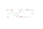
For the below circuit, I have placed multimeter +ve probe at 'B' wrt GND and measures 4V against the expected value of 0V.

Hence I have terminated the 'B' end with 10K to GND temporarily before taking the measurement and reads 0V.

Why this happens?

What happens to the anode of D2 while I connect a multimeter to 'B' end wrt GND ?

I have replaced the 10K temporary resistor with 1M, then again 4V measured !
 

Attachments

  • diode ORing.png
    diode ORing.png
    8.6 KB · Views: 83

Hi

I am not sure what you are asking as I do not understand wrt GND what do you meen by wrt?
 

The phenomenon should be due to the reverse leakage current of D2. In fact the reverse current in a real diode isn't 0 as in an ideal component.

But there is something not clear to me: the 1N4148 diode should exhibit a reverse current of about 30 nA at 25 degC of temperature and 30V (it increases very much with temperature and voltage). This means that across a multimeter (we can estimate an input impedance of rouhgly 10 Mohm) we will have 30nA*10Mohm=0.3V and across a 1Mohm resistor (neglecting the 10Mohm parallel) a voltage of 0.03V.
 
Status
Not open for further replies.

Similar threads

Part and Inventory Search

Welcome to EDABoard.com

Sponsor

Back
Top