Continue to Site

Welcome to EDAboard.com

Welcome to our site! EDAboard.com is an international Electronics Discussion Forum focused on EDA software, circuits, schematics, books, theory, papers, asic, pld, 8051, DSP, Network, RF, Analog Design, PCB, Service Manuals... and a whole lot more! To participate you need to register. Registration is free. Click here to register now.

Spliting voltage across BJTs to avoid breakdown

Status
Not open for further replies.

Knillinux

Newbie level 2
Joined
Aug 17, 2013
Messages
2
Helped
0
Reputation
0
Reaction score
0
Trophy points
1
Activity points
25
Splitting voltage across BJTs to avoid breakdown

Hi,

I'm trying to use a BJT bipolar totem pole to drive a MOSFET gate to an arbitrary voltage, similar to this:

Bipolar-Transistors-For-Mosfet-Gate-Driving-Applications.jpg

However, I am working with +/- 240 V, driving gate capacitances of over 10nF at ~1 MHz, which requires up to 4.5A and hundreds of watts of power in the BJTs. I'm finding it difficult to get power BJTs, especially PNPs, which have a 450+V CE breakdown voltage and can dissipate hundreds of watts of power.

So is it possible to split the voltage between chained BJTs? Here's a design I threw together to do this:
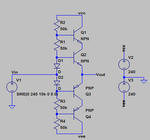
bipolar.png

The resistor ladder splits the voltage evenly between the BJTs so that none of them experience a Vce over 240V. The diodes are to compensate for the Vbe of the BJTs.

It works well in SPICE, but I don't have time to do real life testing before inserting this into my project. The resistor values can be lowered if more current is needed to feed the BJTs.

Are there any potential problems I'm overlooking?
 

Yeah it can be done if you can find a robust way to bias the bases of the BJTs. You'd need much less than 50K for the base bias resistance, especially at high frequencies. Injecting the signal into the base of each transistor using blocking caps would probably help too.

But using paralleled devices is probably easier, and I know it's what most laboratory amps use. For high operating voltages, you could use a driver based on MOSFETs, since there are many high power P channel FETs with Vds of 500V.

Also I wonder what you're trying to accomplish by driving +/-240V into a FET gate, besides destroying it?
 
The FET is part of a MOSFET push-pull driver which is driving a capacitive load. The load charges up as the gate charges, keeping the gate-source voltage within safe limits. Here's an earlier design that I've tested at +/- 50 V:

design.png

The diodes at the input make the MOSFET gates straddle the input voltage, driving the load to within 2-3V of the input voltage. I would use MOSFETs to drive the FET gates, but we need the higher accuracy from the BJTs. Paralleling MOSFETs to drive the load would only increase the gate capacitance we need to drive.

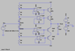
I suppose we could use unity gain op amps to push current into the BJTs while splitting the Vce voltage:

design2.png

We could also replace each of those op amps with more BJT bipolar totem poles, but that just starts to seem ridiculous (at that point we will have gone from 4 BJTs in the original design to 32). I admit, I don't have much experience with this, but there must be a simpler way to bias those BJTs.
 

The diodes at the input make the MOSFET gates straddle the input voltage, driving the load to within 2-3V of the input voltage. I would use MOSFETs to drive the FET gates, but we need the higher accuracy from the BJTs.
Getting high accuracy and low distortion is going to be extremely difficult, unless you use closed loop feedback. At the very least you'll need a slow feedback loop to keep the biasing of the output stage under control once things heat up. A fast feedback loop to control the output voltage will probably be necessary to avoid large offsets and overshoots.
Paralleling MOSFETs to drive the load would only increase the gate capacitance we need to drive.
In the end, you're combining devices to increase power/voltage handling, whether you use series or parallel combinations, the overall result will probably be about the same. The underlying technology is the real determining factor.

Do you actually need devices that can handle such high average power levels? Are you driving a continuous AC waveform into the gate for long periods of time? You may not actually need devices rated for hundreds of watts continuous...
 

Status
Not open for further replies.

Similar threads

Part and Inventory Search

Welcome to EDABoard.com

Sponsor

Back
Top