Continue to Site

Welcome to EDAboard.com

Welcome to our site! EDAboard.com is an international Electronics Discussion Forum focused on EDA software, circuits, schematics, books, theory, papers, asic, pld, 8051, DSP, Network, RF, Analog Design, PCB, Service Manuals... and a whole lot more! To participate you need to register. Registration is free. Click here to register now.

Intercept SMD LED from PCB tracks to connect external simple led (+ and -)

Status
Not open for further replies.

Felipe Salomão

Junior Member level 3
Joined
Aug 7, 2013
Messages
28
Helped
0
Reputation
0
Reaction score
0
Trophy points
1
Activity points
229
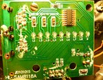
Hi guys, i have project that i will need intercept tracks (SMD LED) from PCB that is working great and connect each smd led to external simple led (positive and negative)..

Here is photo not too much complex PCB..

**broken link removed**

Here is zoom on one of smd leds using digital microscope:
l1.jpg
 

Attachments

  • P1020195.JPG
    P1020195.JPG
    2 MB · Views: 98

Two possibilities come to mind:

1) Solder wires to existing led connections and have them connect to a buffer amplifier with high input impedance, to drive external led.
2) Mount a CdS photocell next to each led, in a light-tight enclosure, and use the resistance change to trigger the external led circuit. But CdS cells might have speed issues. So maybe use a photodiode or other opto device, instead, depending on your application's requirements.

Hi, i prefer solution 1, its too much complicated to make ?
 

EDIT: I couldn't find any specs on the SAM8118 IC that is driving your LEDS. But IF, and ONLY IF, that IC could safely supply enough current, you could POSSIBLY use only a series resistor and LED, for the external circuit for each LED, INSTEAD of something like the circuit I posted below. In that case, you could just put a current-limiting resistor in series with an external LED, and connect that circuit's leads across an existing LED on the PCB. Very simple.

-----

Should be easy, especially if the PCB's power supply can supply the current for the additional LEDs.

You could solder a wire to each of the IC pins that drives an LED and, depending on the "on" and "off" voltages, run each one through a series resistor and then to the gate or base of a switching transistor. The transistor would be between Vsupply and ground (also from the PCB), with a series resistor and LED somewhere in the path between Vsupply and ground.

I will attach a schematic that might work. I used the 2N7000, which is a small transistor. It needs 3 Volts or more on its gate (worst-case max) to turn on. You can use other transistors. You will need to determine the proper value for the resistor in series with the LED, to limit the current.

LED_Buffer.jpg

P.S. If you solder to IC pins, be very careful to not over-heat the IC! Conduct the heat away, maybe like this: Grip the IC pin with a needle-nose pliers, between the IC and where you will solder. A rubber band on the pliers handle could hold it closed for you. If you can find some better place to solder to the PCB, to get the same signals, you should do so.
 
Last edited:

EDIT: I couldn't find any specs on the SAM8118 IC that is driving your LEDS. But IF, and ONLY IF, that IC could safely supply enough current, you could POSSIBLY use only a series resistor and LED, for the external circuit for each LED, INSTEAD of something like the circuit I posted below. In that case, you could just put a current-limiting resistor in series with an external LED, and connect that circuit's leads across an existing LED on the PCB. Very simple.

-----

Should be easy, especially if the PCB's power supply can supply the current for the additional LEDs.

You could solder a wire to each of the IC pins that drives an LED and, depending on the "on" and "off" voltages, run each one through a series resistor and then to the gate or base of a switching transistor. The transistor would be between Vsupply and ground (also from the PCB), with a series resistor and LED somewhere in the path between Vsupply and ground.

I will attach a schematic that might work. I used the 2N7000, which is a small transistor. It needs 3 Volts or more on its gate (worst-case max) to turn on. You can use other transistors. You will need to determine the proper value for the resistor in series with the LED, to limit the current.

View attachment 94691

P.S. If you solder to IC pins, be very careful to not over-heat the IC! Conduct the heat away, maybe like this: Grip the IC pin with a needle-nose pliers, between the IC and where you will solder. A rubber band on the pliers handle could hold it closed for you. If you can find some better place to solder to the PCB, to get the same signals, you should do so.
Hi, after many hours testing (+) IC Pins and (-) 8 contacts on botton of circuit (same that connect RJ45 port), it worked, then i soldered 16 wires direct on pcb then soldered on external led, all work with red leds (2.0v-2.2v), but when i try use green leds (3.0v-3.2v), only 1 of 8 led ouptuts work, then i measured voltage using multimeter on each led ouptut, first one (that worked with green led) was 2.78v and all another ones was only 1.93v, because of this green leds not worked on anothers ouptuts..

Question:
1 - Its possible power on these green leds adding something in circuit ?
2 - Exist some green led that work with 2.0-2.2v (obs: led is 5mm) ?

Thanks !!
 

Assuming that the power supply has enough available current capacity, you can make a small circuit that will trigger from a low voltage like that, to run each of the external LEDs from the power supply, more-directly, instead of through the IC that supplies the on-board LEDs. There are several ways to do it. I will get back to you. Or maybe someone else will beat me to it.

For unusual LED forward voltages for different colors, check at mouser.com or digikey.com , or google.com .

Typically, it's 2.4 volts Vf for red, orange, yellow, then 3.6 Vf for green, blue, etc., all when at 20 mA.

What is your power supply voltage? What is its output VA rating?

Something like the following should work. But you will have to figure out what the value of the current-limiting resistor, R2, should be, based on your power supply voltage and the desired LED current. The circuit should turn on the external LED for control voltages of 1 Volt or higher.

LED_Buf_2N2222.jpg

If you want to run the external LEDS with more than 15 or 20 mA of current, each, then you should probably switch to a larger-size transistor.
 
Last edited:

Status
Not open for further replies.

Similar threads

Part and Inventory Search

Welcome to EDABoard.com

Sponsor

Back
Top