Continue to Site

Welcome to EDAboard.com

Welcome to our site! EDAboard.com is an international Electronics Discussion Forum focused on EDA software, circuits, schematics, books, theory, papers, asic, pld, 8051, DSP, Network, RF, Analog Design, PCB, Service Manuals... and a whole lot more! To participate you need to register. Registration is free. Click here to register now.

Allow a 12v circuit to run when a 2v circuit runs - relay??

Status
Not open for further replies.

itsallgood

Member level 2
Joined
Mar 15, 2002
Messages
48
Helped
0
Reputation
0
Reaction score
0
Trophy points
1,286
Activity points
329
Hi guys,

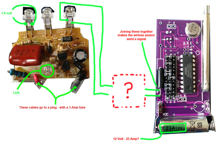
I've got a night light - that powers a 2 volt LED - when it gets dark.


I've got a 12 volt wireless alarm sender.

What I want to do - is join them together. So instead of making the led light up - it allows the 12v alarm sender to send a signal to the alarm box.

From looking around - I think I need a relay?

But I don't understand how to make it work from 2volts.

Could anyone share a simple diagram, and maybe a parts list :)

Thanks so much!!! :)
 

First of all if the LEDs are connected in series (which they should be) then you actually have 3.6 -4.4 volts available. You do not say how you actuate your wireless alarm sounder. If you require to switch the device on, you need to put a transistor in series with the +12V and feed its base via a current limiting resistor fed from the LEDs. Until you give us more data (voltage and current to be switched ), we can't say anymore.
Frank
 
I'm going to check tomorrow to see if the LEDs are in series - to see if I can get the volts up.

I've taken a picture of the two circuits.

The night light circuit runs off a plug -- it just plugs into the wall and has a 3amp fuse.

The wireless sensor runs off a 12v 23 amp battery.


I'm hoping to make night light connect the two points on the wireless senor when the night light comes on.


I'll try and get more data voltage/current/etc tomorrow -- thanks for the help so far chuckey :)


8671205500_1376000104.jpg
 

What's the supply voltage in the night light?

Also measure the supply voltage in the alarm.

At the most basic level, a PNP transistor, in CE configuration would probably do - base goes to top of LEDs, collector to alarm, emitter to night light power (V+).
 
The night light looks like it uses the huge film capacitor to limit the current then rectifies the mains (120VAC or 230VAC).
The tiny battery in the alarm circuit is a 12V model A23 (not 23A) that typically can supply only a few mA for a little while.

Since the night light does not use a transformer then your circuit is deadly if any part can be touched.
 
The night light looks like it uses the huge film capacitor to limit the current then rectifies the mains (120VAC or 230VAC).
The tiny battery in the alarm circuit is a 12V model A23 (not 23A) that typically can supply only a few mA for a little while.

Since the night light does not use a transformer then your circuit is deadly if any part is touched.

Your eyes are better than mine! You need to isolate the two circuits; opto-isolator would do - but there must be power available on the alarm side
 
Your eyes are better than mine!
I got my eyes fixed with new lenses a few years ago when I got blinded with cataracts. Now I can see through the clothing on pretty ladies far away!
Up close the pretty ladies can see me drooling.
 
I have to get the same lenses!
 

Your eyes are better than mine! You need to isolate the two circuits; opto-isolator would do - but there must be power available on the alarm side

An opto-isolator seems like a great idea -- from what I've read - although I don't know how it works - a little 6 leg chip.

There is no power on the alarm side :( only when the alarm signal is being sent.

The only continuous power is on the night light side.


Here was an idea - based on your opto-isolator -- would there be any way to just solder an ldr onto the alarm sensor, that once it picked up the light from the led in the night light -- allowed the alarm circuit to be made?

From what I've read an ldr varies the resistance depending on the amount of light - so it would need to be changed to let the full 12v pass though the alarm with any light from the night light.


Do you think I should scrap the night light circuit - and just try and build my own - non-dangerous circuit?


Thanks for the help guys!
 

Here was an idea - based on your opto-isolator -- would there be any way to just solder an ldr onto the alarm sensor, that once it picked up the light from the led in the night light -- allowed the alarm circuit to be made?

You can do that but there is no power coming in - nothing to trigger the alarm - - the alarm needs a signal, right?

you need power on the alarm side, or a battery powered circuit to trigger the alarm

- - - Updated - - -

Do you think I should scrap the night light circuit - and just try and build my own - non-dangerous circuit?

Maybe it would be simpler for you to change the power supply on the night light - trace it to where the voltage is DC, rip out the components from there back to AC, and then power from a wall-wart.
 

Status
Not open for further replies.

Part and Inventory Search

Welcome to EDABoard.com

Sponsor

Back
Top