Continue to Site

Welcome to EDAboard.com

Welcome to our site! EDAboard.com is an international Electronics Discussion Forum focused on EDA software, circuits, schematics, books, theory, papers, asic, pld, 8051, DSP, Network, RF, Analog Design, PCB, Service Manuals... and a whole lot more! To participate you need to register. Registration is free. Click here to register now.

power on 3 leds (red,blue or green) on toggle switch (3 positions: on/off/on) + relay

Status
Not open for further replies.

Felipe Salomão

Junior Member level 3
Joined
Aug 7, 2013
Messages
28
Helped
0
Reputation
0
Reaction score
0
Trophy points
1
Activity points
229
Goal:
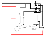
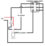
Use 3 position switch to change color of RGB led (4 pins), position 1, color: green, position 2, color blue, position 3, color: red, see diagram, i not tested it yet, only with relay i was able to try make diagram, not know if this will work. If anything is wrong, or would be more simple using another way, please reply with solution.

Obs:
Toggle switch middle pin is when toggle switch is "off", so i tried solve it using relay, i think that i will have problem that when its off, negative signal not go to relay, this way it cant power on blue color led..


See diagram bellow
diagram2.png
 

It is likely a silly question. I am not sure how the 6 terminals (A1, A2, A3 and B1, B2, B3) are connected internally at every position of your 3-position toggle switch.

Is it simply like this?

Position 1: A1 to B1 only
Position 2: A2 to B2 only
Position 3: A3 to B3 only
 

It is likely a silly question. I am not sure how the 6 terminals (A1, A2, A3 and B1, B2, B3) are connected internally at every position of your 3-position toggle switch.

Is it simply like this?

Position 1: A1 to B1 only
Position 2: A2 to B2 only
Position 3: A3 to B3 only

Correct is:

Position 1: A1 to A2 and B1 to B2
Position 2: Nothing
Position 3 A2 to A3 and B2 to B3
 

Thank you for clarifying this type of switch.
Another silly question, sorry. Is it hard to find, on your side, the previous simple switch? Or is there an extra advantage in using, in your project, the one you explained?

But perhaps your question is just an interesting excercise because by using the simple switch, the solution is obvious ;)
 

no, because, this is switch that i have. Its possible have solution using this ? My friend told me that i will need use 2 diodes..
 

The first logical step is to start from position 2 (no connections inside the switch) and the blue LED should be on.
The solution is to connect the blue LED and its current limiting resistor between 12V and ground.
Let us assume that the blue LED resistor is connected to 12V and the blue LED cathode to ground.

Now to the second step, switch position 1:
A2 is connected, as you did, to 12V but A1 to the green LED resistor followed by the green LED whose cathode goes to ground.
But the blue LED should be turned off. Very simple, we connect B1 and B2 to its terminals (shorting its anode and cathode).

We repeat the same for position 3.
A3 goes to the red LED resistor followed by the red LED.
B3 is connected to B1 (shorting again the anode and cathode of the blue LED).
 
Last edited:

Thanks, but it not worked, any led worked using this diagram

it conduct like this: Position 1:
A1 to A2 and B1 to B2
Position 2: Nothing happens (no contact on any pin)
Position 3 A2 to A3 and B2 to B3
 

Thanks, but it not worked, any led worked using this diagram

it conduct like this: Position 1:
A1 to A2 and B1 to B2
Position 2: Nothing happens (no contact on any pin)
Position 3 A2 to A3 and B2 to B3

I think that may your faulty switch or you are not placing it correctly bcs there is two different pins for two different steps.......
 

I think that may your faulty switch or you are not placing it correctly bcs there is two different pins for two different steps.......
I think diagram is wrong, because negative signal (12v), go to B1, B2 and B3 Pin, but it dont have any communication with A1, A2 and A3 pins, how its possible it work ?
 

It seems you didn't like my solution on post #6.
Its drawback is that at switch position 1 or 3, the current of the blue LED is wasted since the LED has to be shorted (to turn off).
 

It seems you didn't like my solution on post #6.
Its drawback is that at switch position 1 or 3, the current of the blue LED is wasted since the LED has to be shorted (to turn off).
Hi, i not tried your solution yet, because venkadeshm posted a diagram and in my last question (another post), his diagram worked great, so i tried this first, after not work, i tried my own diagram (adding diodes), but also not worked, i will read now your solution and try draw diagram to try too.. I had no much time, sorry for not give you feedback, thanks

- - - Updated - - -

Can you post a photo of your switch??

See photo here:

foto 2 (8).JPGfoto 1 (10).JPG

Thanks for help..

---------------

Here my own diagram that i also tried adding diodes:
diagram4.png
 
Last edited:

Hi, i not tried your solution yet, because venkadeshm posted a diagram and in my last question (another post), his diagram worked great, so i tried this first, after not work, i tried my own diagram (adding diodes), but also not worked, i will read now your solution and try draw diagram to try too.. I had no much time, sorry for not give you feedback, thanks

- - - Updated - - -


See photo here:

View attachment 94642View attachment 94643

Thanks for help..

---------------

Here my own diagram that i also tried adding diodes:
View attachment 94644

Then as you said connection I am making the circuit but with relay or without it??

This will work sure....
94647d1376021700-diagram2.png
 

Attachments

  • diagram2.png
    diagram2.png
    13.6 KB · Views: 92

Will try this now. I think that is only possible using relay.. Thank you very much !!
 

Hi, i not tried your solution yet

To save you time, I draw it since it is rather very simple ;)

As you see:

Position 1:
Green is on, connected to 12V (A1 and A2)
Blue is off since it is shorted (B1 and B2)
Red is off

Position 2:
Green is off
Blue is on (short removed)
Red is off

Position 3:
Green is off
Blue is off since it is shorted (B2 and B3)
Red is on, connected to 12V (A2 and A3)
 

Attachments

  • 2P2T-3LED.png
    2P2T-3LED.png
    86.6 KB · Views: 85
Last edited:

Then as you said connection I am making the circuit but with relay or without it??

This will work sure....
94647d1376021700-diagram2.png

That worked perfectly, thank you very much !
Now can you help understand ?

Let see if i understood:

Position 1: led 1 = positive conected aways, negative go from A2 to A1 that go to led,, so led 1 work
position 2: led 2 = positive conected aways, negative is not supplied from B1 and B3, so relay is not energized, so negative signal go to closed and make led 2 work
position 3: led 3 = positive conected aways, negative go from A2 to A3 that go to led, so led 3 work

I think that is it, right ?

But i have few doubts:
1 - last led (conected to relay) never power on together led from position 1 and 3 because, when switch is one of these positions, relay is energized, then last led not power on together.. Right ?
2 - all B columm wont be necessary, if i remove A2 to B2 connection and put move conetion from B1 to A1 and B3 to A3, right ? It would work same way, but less organized.. Its right ?

This type of circuit only is possible using relay when i use this kind of switch ?

Sorry for my english, i am from brazil.. Thank you again

- - - Updated - - -

To save you time, I draw it since it is rather very simple ;)

As you see:

Position 1:
Green is on, connected to 12V (A1 and A2)
Blue is off since it is shorted (B1 and B2)
Red is off

Position 2:
Green is off
Blue is on (short removed)
Red is off

Position 3:
Green is off
Blue is off since it is shorted (B2 and B3)
Red is on, connected to 12V (A2 and A3)

Thank you verry much too, last post worked for me, but i also will make this circuit, because is aways good develop more Knowledge possible, Really thanks for your time..
 

Sorry Felipe, I didn't know that a relay should be included in the solution. Mine, though it works, it doesn't use a relay or diodes.

Added:
I just read your updated post. You are right, it is better knowing more than one solution when possible.
 

Sorry Felipe, I didn't know that a relay should be included in the solution. Mine, though it works, it doesn't use a relay or diodes.

Added:
I just read your updated post. You are right, it is better knowing more than one solution when possible.

For me, more simple solution is better.. So without relay better, but your project use 3 diodes, right ? I also will do that, because, i just started on eletronic "world" to make some hobby (First Person View Ground Station) stuffs, so its better test all solutions to develop Knowledge..
 

3 diodes, right ?

They are the 3 LEDs ;)

Oh sorry... my solution is wrong :(
I forgot you use 4-pin 3-color LED.

I have to redraw it and let the 3 LEDs have a common cathode.

Here it is "2P2T_3-colorLED.png".
 

Attachments

  • 2P2T_3-colorLED.png
    2P2T_3-colorLED.png
    89 KB · Views: 85
Last edited:

Status
Not open for further replies.

Similar threads

Part and Inventory Search

Welcome to EDABoard.com

Sponsor

Back
Top