Continue to Site

Welcome to EDAboard.com

Welcome to our site! EDAboard.com is an international Electronics Discussion Forum focused on EDA software, circuits, schematics, books, theory, papers, asic, pld, 8051, DSP, Network, RF, Analog Design, PCB, Service Manuals... and a whole lot more! To participate you need to register. Registration is free. Click here to register now.

Phase Margin for fully differential OpAmp

Status
Not open for further replies.

Fabien

Full Member level 1
Joined
May 22, 2011
Messages
96
Helped
10
Reputation
20
Reaction score
10
Trophy points
1,288
Location
Grenoble
Activity points
2,025
Hi everyone,

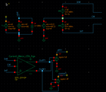
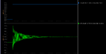
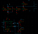
I'm trying to size the miller cap for a fully differential OpAmp. Without the miller cap, the phase is around -230° at 0dB (open loop, differential output). I guess, the OpAmp is not stable, but I try to run some simulations and I'm not able to see it oscillating!
Anyway, I'm just wondering what should be the phase margin? 12° or 45°? (it will result in a lower gain, for sure).
Should I check the phase margin for each independant output (+ and -) or for the differential output (Vout+ - Vout-)??

Thank you for your help.
 

The Phase margin should not affect the DC gain at all.

The better the phase margin, you would see less ringing at the output with step inputs. 45° is a good number.

I used to check for the differential input to differential output.
 

Without the miller cap, the phase is around -230° at 0dB (open loop, differential output). I guess, the OpAmp is not stable, but I try to run some simulations and I'm not able to see it oscillating!
.

The phase margin needs to be determined from the loop gain - not from "open-loop" gain of the amplifier only.
What do you mean with "open loop"?
 

What do you mean with "open loop"?
By "open loop", I mean nothing is connected between the output to the inputs.

Here is my test bench and the gain and phase results (without Miller caps).

nitishn5: for sure it doen't affect the DC gain, but it does for the GBW, so it does for the specifications. GBW should be 5 times the switching frequency.
I tried some pulse waves at the inputs, but no oscillations at the outputs!?
 

Attachments

  • TB_OpAmp.png
    TB_OpAmp.png
    13.3 KB · Views: 186
  • bode_plots.png
    bode_plots.png
    11.4 KB · Views: 187

You need to put a feedback and close the loop before applying the AC signal.
There is a method using ideal inductors of huge values in the feedback path to set the DC operating point and using an ac source to get the loop transfer function plots. I don't remember it exactly but I have seen it in this forum.
 

phase margin should be between 45 to 60 degrees... to achieve good stability in closed loop configuration....

thanks
 
I agree but... if the OpAmp is stable in open loop, it should be in closed loop. As it should be used for SC cap, the OpAmp will work (in a little laps of time) in open loop, and the closed loop also depends on the caps I'll use.
Anyway, I'll check for the inductor method, but I still don't know how to check the OpAmp oscillations regarding to the phase margin...

Fabien, I have the feeling you are not sufficiently familiar with the term "phase margin". Therefore, some basics:

*The phase margin applies to systems with feedback only. It is a measure for "safety" against oscillations in case of a closed loop - but it will be measured/simulated in OPEN loop conditions.
* Thus, you have to open the loop for applying a test signal ac source.
*But the problem is: In many cases, there will be no stable DC operating point under open loop conditions.
*Therefore: Open the loop and place a very large inductor (1 H or more) between both nodes (left and right). Thus, the loop is closed for dc but open for frequencies of interest.
* Then, inject a test voltage into the feedback path using a very large capacitor (1 F or more at one end of the inductor) and measure/simulate the voltage at the other end of the inductor.
* The voltage ratio gives you the loop gain response, which can be evaluated (magnitude and phase) to see the phase margin, which is the phase difference to -360 deg at the point where the magnitude is 0 dB.
 
*The phase margin applies to systems with feedback only. It is a measure for "safety" against oscillations in case of a closed loop - but it will be measured/simulated in OPEN loop conditions.
Sure, that's the reason why I plot the Gain and Phase in open loop. In my simulation, the DC operating point seems to be stable, so if I understand, the inductor is not useful in this case.

The thing is: in OPEN loop, with no miller cap, the phase is far below -180° at 0dB. It seems the OpAmp is not stable! That's what I understand and what I can read in the books. If it's not stable, if I close the loop, the OpAmp may oscillate. So I put a pulse wave in this condition at the inputs, and nothing happen.
So the question is: how to see the system unstable ? Because with a phase margin of 12° (what I set with miller cap) the OpAmp should be stable but may have decreasing oscillations in closed loop. What I can't see.

May be I'm wrong...
 

So I put a pulse wave in this condition at the inputs, and nothing happen.
So the question is: how to see the system unstable ? Because with a phase margin of 12° (what I set with miller cap) the OpAmp should be stable but may have decreasing oscillations in closed loop. What I can't see.

What means "...and nothing happen"? Is the opamp dead? No change of the ouput voltage?
It would be best to show the circuit - otherwise, it is problematic to comment on a circuit that can`t be inspected.
 

    hannover90

    Points: 2
    Helpful Answer Positive Rating
i think, the op-amp's output starts oscillating and ends with decreasing oscillation and finally becomes DC...

Am i correct..? fabien..
 

ithe op-amp's output starts oscillating and ends with decreasing oscillation and finally becomes DC...
It should act like this, that's what I wanted to see but not able to.

What means "...and nothing happen"?

It means nothing is oscillating at the output.

Anyway, guess it's OK, I re run a simulation with the inductor from input to output, and I got the oscillations. Here are the new snapshots.
Now, I think to define the phase margin, I should know what capacitors should be connected in the close loop, right? An then I can define 45°? Am I right?

But, nevertheless, the OpAmp should be unstable, so I expected to see infinite oscillation, not becoming DC!
 

Attachments

  • Simulations_osc.png
    Simulations_osc.png
    12.1 KB · Views: 174
  • TB.png
    TB.png
    19.9 KB · Views: 185

Anyway, guess it's OK, I re run a simulation with the inductor from input to output, and I got the oscillations. Here are the new snapshots.

No - that´s not correct. You have performed a TRAN analysis using the inductors? WRONG!

The inductors are used ONLY for opening the loop ac-wise for the purpose of a loop gain simulation (AC analysis).
More than that, since the ac testsignal to be injected via a large capacitor must be the ONLY signal in the circuit, the "normal" input must be grounded during this simulation.
 
  • Like
Reactions: cxtdyl

    cxtdyl

    Points: 2
    Helpful Answer Positive Rating

    hannover90

    Points: 2
    Helpful Answer Positive Rating
Status
Not open for further replies.

Part and Inventory Search

Welcome to EDABoard.com

Sponsor

Back
Top