Continue to Site

Welcome to EDAboard.com

Welcome to our site! EDAboard.com is an international Electronics Discussion Forum focused on EDA software, circuits, schematics, books, theory, papers, asic, pld, 8051, DSP, Network, RF, Analog Design, PCB, Service Manuals... and a whole lot more! To participate you need to register. Registration is free. Click here to register now.

Lm1117 (3.3v) become very hot

Status
Not open for further replies.

Sharagim

Advanced Member level 4
Joined
Feb 6, 2011
Messages
112
Helped
0
Reputation
0
Reaction score
0
Trophy points
1,296
Activity points
2,058
Hi,
I am working on xMega project andknow I have problem.
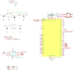
as you see in schematic I have a lm1117 which converting 5v to 3.3v.
I am using this 3.3v to feed a enc28j60 module and a xmega64a3(at 32MHZ).
My lm1117 become very hot after a few seconds !!! is this normal?!

BR,
g66209.png
 

I think you should thus 0.1uf cap in every power.
 

According to datasheet for lm1117 we should use this caps.
 

My datasheet for this part specifies a 10uF tantalum capacitor for the output. These have very low ESR (resistance). I'm guessing the 100uF capacitor you show is a common electrolytic, which will have much higher ESR.

LDO regulators like these are more complex than an average linear regulator, and so have a slower feedback loop; which gives them a tendency to oscillate if specific conditions are not met on the output pin. Especially ESR! I've designed several as an exercise in SPICE and found ESR of the output caps to be absolutely critical to stability.

If you don't have the tantalum cap, try using a ceramic cap in parallel as suggested. It's often sufficient, though you may need a 1uF or 10uF, instead of a 0.1uF.

And of course, rule out other possibilities if you haven't already, like excessive current drain for example.
 

What is the the maximum power consumption of you total circuit?

I think you draw the more from the LM1117 regulator.

And check total efficiency of the regulator.
 

I changed the output cap with 10uF tantalum but nothing changed.
When I measuring total power consumption the multimeter show 130mA but the board not working properly I mean my enc28j60 not responding to requests (seems it need more power) .
I post the whole schematic here maybe it help to find the problem.
 

Attachments

  • g28243.png
    g28243.png
    296.3 KB · Views: 131

Did you measure the output voltage of the LM1117?

If it gets very hot it sounds like you may have it connected incorrectly. Oscillations would likely not do that. Double check the pinout of the LM1117 and the wiring.
 

Thanks for replies.
I attached the pcb design of that section below. the 5v is coming from lm2576 so it is like this :
[ Switching power supply 7.5V ---> lm2576 (5V) ---> lm1117 (3.3V) ]
For making myself sure about it ,I disconnect lm2676 from lm1117 and use another 5V supply and connect it directly to it and same problem.
Something which making me suspected now is my track width around lm1117 (0.3mm), maybe they are not wide enough to help it bypass heat!?

BR,
 

Status
Not open for further replies.

Part and Inventory Search

Welcome to EDABoard.com

Sponsor

Back
Top