Continue to Site

Welcome to EDAboard.com

Welcome to our site! EDAboard.com is an international Electronics Discussion Forum focused on EDA software, circuits, schematics, books, theory, papers, asic, pld, 8051, DSP, Network, RF, Analog Design, PCB, Service Manuals... and a whole lot more! To participate you need to register. Registration is free. Click here to register now.

[help] trying to build a light system

Status
Not open for further replies.

STINGERX

Junior Member level 3
Joined
May 14, 2013
Messages
25
Helped
0
Reputation
0
Reaction score
0
Trophy points
1,281
Activity points
1,465
hi,
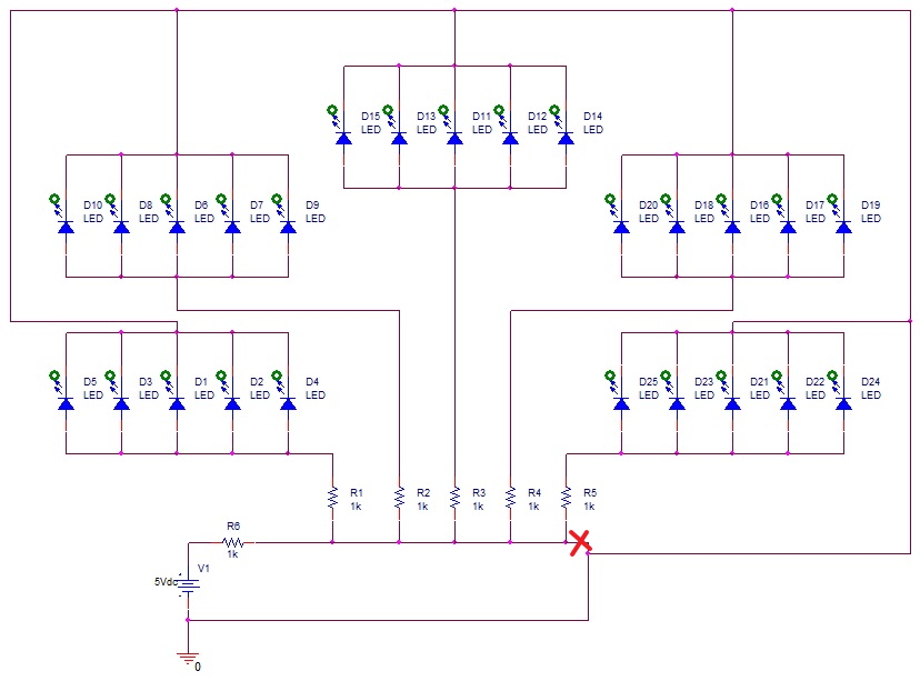
as you can see from here:
Untitled.jpgUntitled.jpg
Pspice shows me this errors in the simulation:

Code:
**** INCLUDING SCHEMATIC1.net ****
* source sys
V_V1         N00149 0 5Vdc
R_R1         0 N00437  1k TC=0,0 
R_R2         0 N00783  1k TC=0,0 
R_R3         0 N01174  1k TC=0,0 
R_R4         0 N01530  1k TC=0,0 
R_R5         0 N01942  1k TC=0,0 
R_R6         N00149 0  1k TC=0,0 

**** RESUMING sys.cir ****
.END

ERROR -- Less than 2 connections at node N00437
ERROR -- Less than 2 connections at node N00783
ERROR -- Less than 2 connections at node N01174
ERROR -- Less than 2 connections at node N01530
ERROR -- Less than 2 connections at node N01942

am i doing this the wrong way?
i'm trying to design this so the voltage in each junction will be even

any suggestions?
 

What is the Vd of the LEDS? Are all the LEDs the same?

I am puzzled when you say you want the voltage 'even' at each junction. Is it the same voltage or same brightness?

You should NOT wire LEDs in parallel [unless they are 'perfectly' matched] else one will hog the current and burn out.


>>>IF<<< the Vd is from 1V6 to 2V0 you can wire two in series, and place a resistor to limit the current for each set of two
else you will need a resistor for each LED.
 

Besides the points made by kam1787, if you take a closer look at the schematic, essentially you have a 5v power supply (V1) powering a 1kΩ resistor (R6), the rest of the circuit is irrelevant due to the bridge connection (short) marked by the red X in the attached schematic.

This bridge connection (short) is also the reason for the SPICE errors.


BigDog
 

What happened to the op????????????
 

Status
Not open for further replies.

Similar threads

Part and Inventory Search

Welcome to EDABoard.com

Sponsor

Back
Top