Continue to Site

Welcome to EDAboard.com

Welcome to our site! EDAboard.com is an international Electronics Discussion Forum focused on EDA software, circuits, schematics, books, theory, papers, asic, pld, 8051, DSP, Network, RF, Analog Design, PCB, Service Manuals... and a whole lot more! To participate you need to register. Registration is free. Click here to register now.

RFID simulation HFSS

Status
Not open for further replies.

LORDALEX

Newbie level 6
Joined
Aug 1, 2012
Messages
14
Helped
4
Reputation
8
Reaction score
4
Trophy points
1,283
Activity points
1,383
Hello,
Indeed, i am working on UHF tag antenna and i simulat them using HFSS simulator. For excitation, i put a 50 Ohm lumped port ( idont know if is it good or false) but what i have difficulty understanding how can i extract the internal impedance of the antenna. In another, mean, did the fact to have a port of 50 Ohm can disturb the internal impedance of the antenna and thus get a wrong answer? or i must to put the impedance of the microchip and then adapt the antenna? please help me
 

Your port impedance has to match with ur antenna input impedance, if not due to mismatch u will have a bad return loss. generally since the sources are of 50 ohm, and antennas could be of other than 50 ohm impedance, a matching network is used. so u need to first evaluate what ur antenna impedance would be theoretically and simulate accordingly..
 

thx you for your helpful answer,
another thing please about simulation using HFSS, why in some case the return loss can be improved by matching the impedance of the port with the impedance of the antenna while in other cas, the return loss is unchanged (is missmatched) whatever is the impedance?
 

I dont knw what exactly is the second case that u r speaking off, coz irrespective of any antenna characteristics or radiation capabilities if its impedance is matched return loss is good..


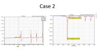
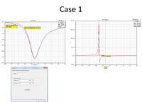
here an images of what i have said.
 
Well as ur images depict, ur antenna impedance seem to be near to 6 ohms and so U have a good return loss, the other case that u have taken of 50 ohms, u dont have proper returnloss as there is a mismatch. As for ur point of why the returnloss is same for any other value other than 6ohm, A Miss match is a miss match whether it is by 50ohm or 100, The return loss cannot be same if ur port impedance is 50 and 100, they both will be different atleast slightly. If u plot them with the case of matched one, then u surely wont be able to say the diff, but plot them separately U should be able to see that there is a slight diff in the level of return loss for different mismatches..!!
 

Hi Lordalex ,

I am also doing the RFID Tag simulation, But i am a newbie HFSS, I have been using CSt Microwave.Can you help me in simulating RFID tag structure I have built the structure Using CST , Now i would like to do it in HFSS. I studied several tutorials but all wer given with Infinite Ground, but in the case of RFID we never use Ground Plane. So i dont have any clue to simulate the RFID loop structure! pls help me ..
 

Hello govindram,
i advise you to use HFSS antenna design Kit. it is a software with HFSS that help you to automatically draw the antenna. You just should determine your frequency band and the antenna topology.
Normally the procedure to design an antenna with infinite ground using HFSS is the same with finite ground or without ground.
I attached an example of dipole antenna, very used in RFID solution.
 

Attachments

  • AntenneDipoleRef.rar
    40.8 KB · Views: 158

Thanks LORDALEX,

I have a loop structure which i need to simulate ...but without ground...i have a doubt that structure without ground will have different resonant frequency and radiation pattern and With ground will have diffrent radiation properties pls clarify
 

Hi,
Indeed, it is normally that you find two different behavior. A loop antenna is used normally without a ground plane and if you put a ground plane close to antenna you will loss adaptation and radiation. if you want, draw the antenna in HFSS and i can check it for you if you want. Unfotunatly, i dont have an example of loop antenna :(.
 
Thanks LoRDAlex. I have attached a loop structure to resonate at 868 for a tag on wood. Now i would like to see the results on HFSS and would want to see the impedance. This is the structure originally i created in CST and imported from it in SAT model. So may be i havent applied Perfect E and Sheet, Can you pls look into it!and also impedance .

Thank you
 

Attachments

  • woodtag.zip
    110 KB · Views: 112

Hello, At first, your antena is not a loop antenna, indeed it is a folded dipole with a t-match ( for match wit complex impedance).
When you simulate a antenna,you must to place vaccum at at least lambda/4 from all radiation surfaces.
Secondly, if you want to simulate radiation, you should enter your radiation boundaries. Right click on radiation, then insert farfield.
For the excitation you must to put the conjugate of your chip impedance.
in the attachment, i have did all this modification.
 

Attachments

  • Triloop.rar
    76.9 KB · Views: 121
Hi LORDALEX,

I am Using HFSS 13 and i am unable to open the structure. Is their compatible version try it out?
 

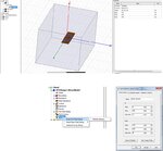
I am sorry but i dont have a earlier version so i attach an image in which i explain what i have modified


- - - Updated - - -
 

Attachments

  • Modifying.jpg
    Modifying.jpg
    111.9 KB · Views: 167
Status
Not open for further replies.

Similar threads

Part and Inventory Search

Welcome to EDABoard.com

Sponsor

Back
Top