deepakchikane
Full Member level 3
- Joined
- Jul 17, 2012
- Messages
- 178
- Helped
- 2
- Reputation
- 4
- Reaction score
- 2
- Trophy points
- 1,298
- Location
- Mumbai, Maharashtra, India, India
- Activity points
- 2,623
Follow along with the video below to see how to install our site as a web app on your home screen.
Note: This feature may not be available in some browsers.
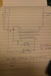
Which triac? T1 or T2 (or both)?
Without understanding your circuit's intended operation (what is the transformer for? What's it's ratio? What's the supply voltage/impedance?) a warning flag has popped up in my mind about your design exceeding the triac(s) di/dt and/or dV/dt limits. Series resistance (perhaps with some inductance) with whichever device is switching will undoubtedly help...
I suspect what's happening is that on application of power, the resulting high dV/dt rate (across their MTx terminals) is triggering the triacs into conduction. Very large currents will then flow through the conducting triacs from the [low impedance] mains supply, undoubtedly killing them (quickly!)
Try adding a resistance (a 100W incandescent globe is a good indicator/indestructable load resistor) between the triacs, perhaps combined with 100 uH(ish)+ of inductance to limit the commutating currents/dI/dt. This will let you get a feel for the intended switching behaviour without destroying any more triacs. You can remove them later (or have a relay switch them out if they prove essential to surviving initial turn-on/mains transients) if you like.
Put a .01 MF capacitor* inseries with a 100 ohm resistor across each triac. Now when the mains is switched on the very fast switching edge sends current down throuth the snubber network and not into the gate of a triac.
* make sure it is rated for 230 V AC and is a type X or Y - rated fro mains use.
Frank
Xc = 10^6/ 2 x PI X .01 X 50 ~ 10^6/ PI ~ 300 k , So resistor current should be 240/300 mA ~ .8 mA, P100 = 100 X .64 micro watts or 6.4 mW . its good to see that the 100R resistor is soaking up power because the dissipation from the steady state AC is only 6.4 mW. However there should be no real heat, just a burst of power during the first few 1/2 cycles of the mains when powering or depowering. If its running hot, either the cap is too big in value, or its leaky, or there is something putting big transients down the AC line.
Frank
Hi , my guess is also a dv/dt failure. Do not let the gates floating . Put some RC protection circuit ( use a high power resistor not a 250mW one) ,connect the gates to cathodes and see if it still fails. If not , use some low impedance driver to drive T1 and T2. I really don't understand the use of T1. Witch is 220V side and witch 16V side on the transformer? Do you supply this circuit with 220V?
chukey:At switch on, you have mains fed via the 16v winding to the load. if T1 is not already turned on, there will be a massive voltage generated by the 230V winding applied to T1 and T2. So the first thing to think about is to stop the full 230v being applied across the 16V winding. 16V rms ~ 46V p-p, put some 50V high power zeners across the 16v winding?, or some sort of delay circuit, to make sure T1 is ON before mains is applied. You could apply this technique to the secondary instead, this is what the T1 snubber is doing, the high voltage transient is being soaked up via the cap then putting real power into the resistor.
i am not sure what the circuit is mean't to do, either to switch the outgoing voltage to the load up by 16V, or to reduce it by the magic 16 V?
Frank
The circuit operation mode is still partly unclear.
How about load current, voltage induced in the primary winding by the load current? How do you assure that the primary voltage doesn't exceed the maximum triac voltage?
Regarding triac triggering, what's the trigger circuit, do you perform zero voltage switching? Otherwise the other triac will be most likely triggered by exceeding dV/dt rating, causing catastrophic failure of both triacs.
You're confusing package insulation with triac voltage blocking.BTA 24 is having 2500vrms blocking capacity
You're confusing package insulation with triac voltage blocking.
Anyway, maximum dV/dt isn't a matter of voltage rating as such. If you are igniting one triac at the wrong time, you'll risk dV/dt induced triggering of the other one.
Yes, that's what I did. I'm referring to the ST datasheet. But 2500 V blocking voltage of a triac is absurd anyway.fvm
please read the bta 24 datasheets...