Continue to Site

Welcome to EDAboard.com

Welcome to our site! EDAboard.com is an international Electronics Discussion Forum focused on EDA software, circuits, schematics, books, theory, papers, asic, pld, 8051, DSP, Network, RF, Analog Design, PCB, Service Manuals... and a whole lot more! To participate you need to register. Registration is free. Click here to register now.

voltage level detector

Status
Not open for further replies.

p72

Member level 3
Joined
Jan 2, 2013
Messages
58
Helped
1
Reputation
2
Reaction score
1
Trophy points
1,288
Activity points
1,717
Hi All,

I am looking for help to design voltage level detector circuit. Not something specific project related.
How to detect different voltage level? Need to detect at two points, first is: between 20-30Vdc range and second between 80-300Vac. yes, one is dc and other is ac. Is it possible to detect voltage between ac and dc?
Is there any other method than voltage detector?

Thank you,
pj
 

Are you just looking for an on/off type detection or do you need to know the value? AC is alternating current, DC is direct current(think Doesn't Change), there's no in between. Google voltage detector circuit and you'll find several different circuits that will work, depending on what you are measuring.
 

Hi,
Thanks for the response.
I would like to design detector that can detect AC and DC. I don't want to measure numbers. And I know that my DC is always between 20-30V and AC is always in range of 80-300V.

I tried on google but mostly those are for small voltage levels.
Could we have something else? like frequency detector? Because AC has always positive and negative cycle and DC has flat voltage level.

Thank you,
pj
 

I am not sure I understand. You want one circuit to do either, or one circuit to detect the voltage difference between DC and AC circuits?

First thing that comes to mind it is have a full-wave rectifier on the AC side, then a resistor voltage divider to bring the voltage down to a reasonable level. If you are using op-amps to compare, then also have a voltage divider for the DC side.

I'd include over-voltage protection on the AC side as well.
 

Hi,
First you can convert the AC voltage to DC voltage by using bridge rectifier , and step down the voltage levels to smaller values where you can feed these to amplifier. Amplifier output to be connected to ADC to detect the voltage levels.
Make sure that the charging capacitor at bridge rectifier output should be discharged quickly to detect the next level of voltage.
 

Thank you very much to everyone who replied.

Here is my block diagram of what I would like to do. Please see attached.
I agreed that first I need to convert AC in to DC by using bridge rectifier but my problem is, how do i know that which voltage is coming in? What if DC is coming in instead of AC?
powersupply.jpg

Thank you,
p72
 

Attachments

  • ps.jpg
    ps.jpg
    49.2 KB · Views: 66

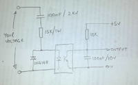
Use this:


Not an op-amp in sight. The output will be 5V with DC present at the input and almost zero with AC present.

Any opto-coupler should work and it also gives your circuit good isolation from the AC/DC input.

Brian.
 

Do you want it to provide power or compare voltage?!

Bridge rectifier will work with DC, with the advantage of giving the right polarity.
 

Hi Brian,
I don't get it your point. Could you please explain in detail?
Thank you,
pj
 

I'm assuming your input can be AC or DC on the same wires, otherwise rectify the AC, scale it with a potential divider and compare it with the DC scaled with a second potential divider. Even if you have two separate inputs, the circuit will work to check for AC presence.

The schematic works by utilizing the reactance of the capacitor to allow AC to reach the opto-coupler and also the capacitor's property of blocking DC. When DC is applied, apart from a very short pulse of current as the capacitor charges, no current flows into the opto-coupler LED so the output side goes to a logic high level.

When AC is applied, the capacitor allows current to flow, the diode conducts on one half cycle and the LED inside the opto-coupler on the other. The output side of the opto-coupler will go low when the LED lights and the capacitor across it will be discharged, taking the output to logic low. It will actually be a low level pulsing signal at the output because the capacitor will try to recharge when the opto-coupler is turned off but with suitable time constant it should stay below logic low level.

The bonus to the circuit is it gives safety isolation between the voltage you are checking and whatever follows it.

Brian.
 

Hi betwixt,
Thanks for the explanation. I was still not clear about the method.
Can I do this?
I am trying to build switching circuit by using AC Relay as wanted to switch AC voltage v/s DC voltage.
I have two inputs, one is AC (80-280 V) and other is DC (20-30 V). Anyone can be present at a time and Relay will decide itself which one is coming in. How?
I would like to set Relay in "default mode" for DC supply. That means if I applied AC voltage to the Relay, it should switch Relay position/contacts and goes into further stage. For DC voltage, I am thinking to put diode before relay, which will block DC and will not allow to pass it through the Relay. As a result, Relay will stay in its original (default) position and DC will pass without entering into Relay.
I wanted to make sure, does this make sense? Second question: - Can I find this kind of Relay easily for the same purpose?

Please help me or give me suggestions?
I really appreciated any input from anyone.

Thank you,
p72
 

is the polarity of the DC always the same?
 

is the polarity of the DC always the same?

Good question kam!! It is dual polarity, should be same but not all the time!!!!
What if polarity stays same all the time? Does it duable?
Thanks,
p72
 

Good question kam!! It is dual polarity, should be same but not all the time!!!!

A capacitor will block DC, but allow rectified AC to pass.

How will you power the relay? from the incoming signal, or another power supply?


perhaps like this


in >------- capacitor ------- voltage divider and limiter----CC [perhaps CE as well]-------relay
 

A capacitor will block DC, but allow rectified AC to pass.

How will you power the relay? from the incoming signal, or another power supply?


perhaps like this


in >------- capacitor ------- voltage divider and limiter----CC [perhaps CE as well]-------relay
Can I use same incoming AC supply to power up relay?
Whats the reason behind voltage divider and limiter?
 

Can I use same incoming AC supply to power up relay?

i have no idea - you never said what power is the AC, nor did you say the current needed by the relay!

Whats the reason behind voltage divider and limiter?

First you said to COMPARE voltages, so a voltage divider would be appropriate.

You never said how the inputs would be used.

Can your circuit, after the relay, handle up to 280VAC? If not, then you need a way to limit the voltage.


Part of the problem, is that you have not been clear enough, nor consistent enough on what you want.
 

Hi kam,
I have said main AC so freq is 60hz and current depends on relay whichever I choose.

Yes, you are correct that I said voltage compartor earlier but I have modified my post in #11 .
After relay circuit I will drop down voltage by transformer and rectifier. So I will get DC voltage as similar as original DC.
I will draw block diagram soon.

Thanks
 

Hi kam,
I have said main AC so freq is 60hz and current depends on relay whichever I choose.

Actually you did not say main or mains...............
 

Here is the upper-level circuit diagram of what I wanted to do. (I know that circuit is not 100% correct.).

View attachment ac-dc-ps-circuit.pdf

I am not sure how circuit will behave when I apply DC voltage. I need help for DC path. And I am assuming that relay is rated for AC voltages. I can get this kind of relay, correct?
Will this circuit work for what I am trying to do?

Any suggestion or guidance on this circuit will be appreciated.
Thank you,
p72
 

I think I can tell you with some certainty. The circuit as drawn will not work with any AC or DC input because the supply is shorted out!

Am I right in assuming what you are attempting is to switch a backup DC suppy on when the AC fails?

Brian.
 

Status
Not open for further replies.

Similar threads

Part and Inventory Search

Welcome to EDABoard.com

Sponsor

Back
Top