Continue to Site

Welcome to EDAboard.com

Welcome to our site! EDAboard.com is an international Electronics Discussion Forum focused on EDA software, circuits, schematics, books, theory, papers, asic, pld, 8051, DSP, Network, RF, Analog Design, PCB, Service Manuals... and a whole lot more! To participate you need to register. Registration is free. Click here to register now.

TRIAC Interface Circuit Help

Status
Not open for further replies.

drcoyle65

Newbie level 2
Joined
Jul 1, 2013
Messages
2
Helped
0
Reputation
0
Reaction score
0
Trophy points
1
Activity points
22
8217509000_1353486022.jpg


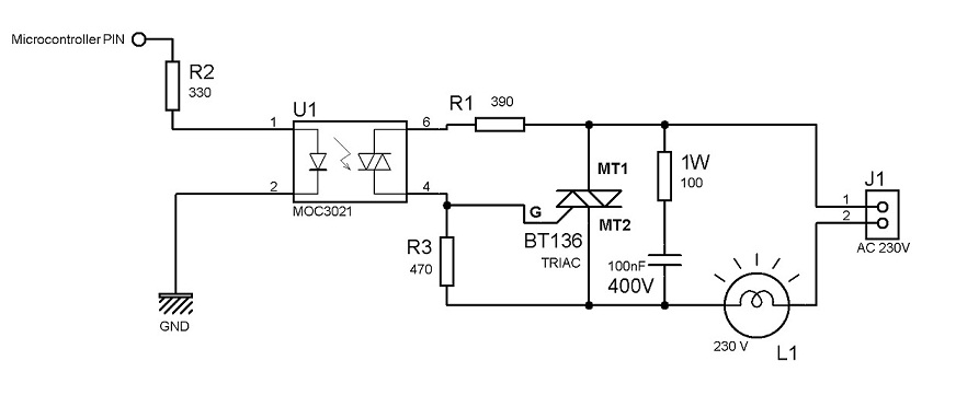
I have several questions about this TRIAC interface circuit. I am trying to build a circuit that is very similar, except that it will primarily use 120V 60Hz. It is fine if it works for 120/230V and 50/60Hz. The incandescent bulb will be no more than 75W.
My first question is about the MOC3021 and MT136 devices. There seems to be several varieties, especially with the MT136. Are there specific ones that you would recommend?
What are the wattage rating of R1, R2, and R3? Are they 1/4 watt or 1/2 watt?
What gauge wire are you using for the main power?
Would it be easily adaptable to have the output go to an outlet and then plug the corded light into the outlet?
The input to the circuit is coming from the PWM section of a microprocessor. Is the triac triggered from the positive or negative portion of the waveform?

Any other information would be greatly appreciated.
 

Hi,

This circuit will works.but I am not sure that this is controllable.It will be controllable if you remove the R3 resistor and interchange the triac main terminals. ( Means replace MT1 with MT2 & replace MT2 to MT1).
 

Status
Not open for further replies.

Similar threads

Part and Inventory Search

Welcome to EDABoard.com

Sponsor

Back
Top