Continue to Site

Welcome to EDAboard.com

Welcome to our site! EDAboard.com is an international Electronics Discussion Forum focused on EDA software, circuits, schematics, books, theory, papers, asic, pld, 8051, DSP, Network, RF, Analog Design, PCB, Service Manuals... and a whole lot more! To participate you need to register. Registration is free. Click here to register now.

Loop Filter Poles and Zeros

Status
Not open for further replies.

Engineer4ever

Member level 3
Joined
Feb 2, 2013
Messages
67
Helped
1
Reputation
2
Reaction score
1
Trophy points
1,288
Activity points
1,748
Hi,

How can I determine the formula of poles and zero for that filter? I am a little confused.

Thanks in advance,
 

Attachments

  • LF.png
    LF.png
    3.3 KB · Views: 80

Are you sure that there is no resistance or such between D0 & C1 or VCO
 

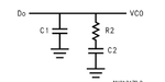
Poles and zeros are derived from the transfer function in the s-domain.
Thus, you need the output-to-input ratio.
What is your input? I assume it is a current - correct?
 

This is a loop filter used in the PLL loop. The input is current and the output is the control voltage of the VCO
 

This is a loop filter used in the PLL loop. The input is current and the output is the control voltage of the VCO

Yes - that`s what I have expected.
As said - derive the transfer function Vout/Iin and determine poles and zeros. This shouldn`t be too much work.
 

Status
Not open for further replies.

Part and Inventory Search

Welcome to EDABoard.com

Sponsor

Back
Top