Continue to Site

Welcome to EDAboard.com

Welcome to our site! EDAboard.com is an international Electronics Discussion Forum focused on EDA software, circuits, schematics, books, theory, papers, asic, pld, 8051, DSP, Network, RF, Analog Design, PCB, Service Manuals... and a whole lot more! To participate you need to register. Registration is free. Click here to register now.

Dual polarity square wave generator

Status
Not open for further replies.

Elex-factor

Junior Member level 1
Joined
Jul 12, 2011
Messages
18
Helped
0
Reputation
0
Reaction score
0
Trophy points
1,281
Location
Seoul, Korea
Activity points
1,445
Hi

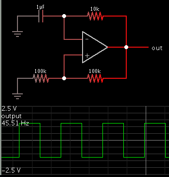
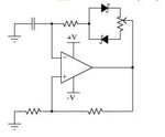
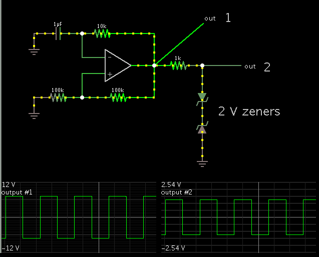
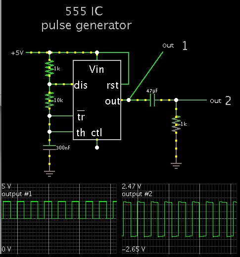
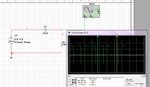
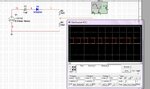
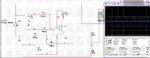
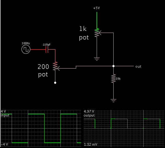
I am using a timer 555 ic to generate a square wave with a peak to peak voltage of 5 V. The square wave that i obtained has a peak to peak voltage range between 0 V and 5 V. However, I need a dual polarity square wave from -2.5 V to +2.5 V. How can I achieve that and what circuit should I add with the 555 ic? Please guide me on the right path.
 

You can turn DC pulses into AC square waves by installing a series capacitor of sufficient value.

Or you can make a relaxation oscillator based on an op amp. To get bipolar 2.5V, you'll need to adjust the power supply to the correct volt level. Or use the right combination of diodes, back-to-back.

9142248100_1372177543.png
 

@BradtheRad: By saying back to back diodes,are saying like the one attached so that you are capable of varying duty cycle by moving the wiper.
The first one with the series capacitor are you saying in the (0-5)V DC pulse,DC offset 2.5V would be blocked ???

Would the said two work at high frequency ???
 

Attachments

  • Capture.JPG
    Capture.JPG
    12.6 KB · Views: 197

@BradtheRad: By saying back to back diodes,are saying like the one attached so that you are capable of varying duty cycle by moving the wiper.

Zeners back-to-back. The resulting amplitude is the zener value plus 0.6V.


Diodes (or led's) arranged anti-parallel.


It could be difficult to obtain exactly 2.5V amplitude. A low ohm resistor can be added to 'bend' the value a little.

As a matter of fact, if the op amp output is at an unchanging volt amplitude, a simple resistor divider could do the job without diodes.

The first one with the series capacitor are you saying in the (0-5)V DC pulse,DC offset 2.5V would be blocked ???

Using a series capacitor to turn DC pulses into AC square waves. (The resistor to ground is necessary.)


Would the said two work at high frequency ???

Only as high as component specs permit. If we try to go faster than that, the waveforms will start to deteriorate, of course.
 
Zeners back-to-back. The resulting amplitude is the zener value plus 0.6V.


Diodes (or led's) arranged anti-parallel.


It could be difficult to obtain exactly 2.5V amplitude. A low ohm resistor can be added to 'bend' the value a little.

As a matter of fact, if the op amp output is at an unchanging volt amplitude, a simple resistor divider could do the job without diodes.


Using a series capacitor to turn DC pulses into AC square waves. (The resistor to ground is necessary.)


Only as high as component specs permit. If we try to go faster than that, the waveforms will start to deteriorate, of course.

Thanks BradtheRad..The last circuit with a series capacitor worked for me. But do we need to change the capacitor and resistor value for different voltage input? For e.g. I tested using 12V input and got the square wave from -6 V to +6 V with the same capacitor and resistor value. If I give 15 V input, do I need to change the capacitor and resistor values?
 

You want +7.5 & -7.5 from 15-0 i/p right.You don't need to change them.
 

Attachments

  • Capture.JPG
    Capture.JPG
    141.5 KB · Views: 213

Hey dude just change the ground level.....
with this circuit add a 10k, 10k series combination and connect between +5v and -ve. now the center of the resistors is your new ground and measure the output from this ground....
 

But do we need to change the capacitor and resistor value for different voltage input? For e.g. I tested using 12V input and got the square wave from -6 V to +6 V with the same capacitor and resistor value. If I give 15 V input, do I need to change the capacitor and resistor values?

This method just happens to work because your specs did not result in changing the amplitude, but only to center the waveform around the zero line.

As Rahdirs pointed out in post 9, you will get +7.5V and -7.5 from 15V DC pulses.

What I forgot to point out is that the duty cycle needs to be 50 percent, in order to get symmetrical AC square waves. To get this from the 555 pulse generator schematic above, you will need to add a couple more components.
 

I have one more question. What if we need to step up the voltage level from the range of -4 V to +4 V to a microcontroller compatible voltage level between 0 and 5 V? Can we just use a resistor circuit or is there any other better way? Please suggest me some solutions.
 

  • To convert bipolar square-wave to unipolar,i used an op-amp to bring it to (8-0)V & then use a resistive divider to bring it down to (5-0)V as in fig.2. The above method works fine,but you would need a variable PSU.
  • So,to simplify it i used a passive circuit,a diode to clip off the negative values & a capacitor as in fig.1.You'll need a big capacitor to get to 1 Hz into most loads.
  • or just use a 311 comparator.
 

Attachments

  • Capture1.JPG
    Capture1.JPG
    156.8 KB · Views: 192
  • Capture.JPG
    Capture.JPG
    172.9 KB · Views: 208

You'll use a resistive divider to convert bipolar to unipolar square wave ???? How do you intend to bring (-4 - 4) V to (0 - 5)V
 

I do know that you can use clamper to shift DC value.Similar to adding offset like post #14.
I wanted to know how he wants to use only resistive divider,only using passive resistances it is definitely not positive
 

untitled.JPG
You'll use a resistive divider to convert bipolar to unipolar square wave ???? How do you intend to bring (-4 - 4) V to (0 - 5)V
Hi rahdirs,
I answered for the very top question 0 - 5V to -2.5V - 2.5V. So why i said to use resistive devider. two resistors s sufficient....
sorry for late reaction.................
 
Last edited:

What if we need to step up the voltage level from the range of -4 V to +4 V to a microcontroller compatible voltage level between 0 and 5 V? Can we just use a resistor circuit or is there any other better way? Please suggest me some solutions.

A combination of potentiometers can do this. One potentiometer conveys a portion of a 5V supply V.

The capacitor blocks DC from flowing back toward your input signal. However the capacitor can distort a square waveform.

Screenshot:


Status
Not open for further replies.

Similar threads

Part and Inventory Search

Welcome to EDABoard.com

Sponsor

Back
Top