Continue to Site

Welcome to EDAboard.com

Welcome to our site! EDAboard.com is an international Electronics Discussion Forum focused on EDA software, circuits, schematics, books, theory, papers, asic, pld, 8051, DSP, Network, RF, Analog Design, PCB, Service Manuals... and a whole lot more! To participate you need to register. Registration is free. Click here to register now.

Data Logger PIC16F877A

Status
Not open for further replies.

ma10adi

Newbie level 3
Joined
Jun 23, 2013
Messages
4
Helped
0
Reputation
0
Reaction score
0
Trophy points
1
Activity points
36
Hi

I have to design a Data Logger programusing mikroC PRO to run on the EasyPIC5 board (with PIC 16F877A microcontroller). I also have to use a 2-line LCD for display.

Here is what i have been given:

The program will take measurements from Analogue Port AN0 at regular intervals, and save the raw data to
EEPROM. The user should be able to select any of 6 memory banks to store the results of a logging session,
and should be able to set the time interval between readings at 1 second, 2 seconds, 5 seconds or 10
seconds. The number of readings taken in each logging session should be set to 5, but should be alterable from a #define in the first few lines of the program. Another #define should be used to specify the total number of memory banks (set to 6).

Having quite a bit of trouble with this.

Any help would be appreciated.
 

Hi ma10adi and welcome to EDABoard forum,

You plan to use external EEPROMs with I²C ?

What you consider under "memory banks" ?

Post your current code if you have.


Best regards,
Peter

;-)
 

i defined READINGS as 6
Code:
i=1;
while(!PORTC.F0 && i < READINGS) {
            i = i+ 1;
            result = ADC_Read(0);          // Read ADC channel 0
            LCD_int2(1,5,result,4);      
          if(time == 1){
            EEPROM_Write(255,result);
            Delay_ms(1000);             
          }
          if(time == 2){
            EEPROM_Write(255,result);
            Delay_ms(2000);              
          }
          if(time == 5){
            EEPROM_Write(255,result);
            Delay_ms(5000);               
          }
          if(time == 10){
            EEPROM_Write(255,result);
            Delay_ms(10000);              
          }

        }

Under every memory bank there should 5 different reading from one logging session of analogue data and time.

In the above code i only write the reading at same address everytime.

but i am lost in setting memory banks to 8 and saving the logging session to the banks and retrieving data from the memory banks...in that part i have not code at all..

thanks upfront for any help :)
 

What you mean under "banks" ?

If you want to use internal uC EEPROMs MikroC you should use EEPROM library and EEPROM_Write(address, data) routine.

https://www.mikroe.com/download/eng...c/pro/pic/help/eeprom_library.htm#eeprom_read

Examples:
EEPROM_Write(0x32, 19);
take = EEPROM_Read(0x3F);

Note:
Ensure minimum 20ms delay between successive use of routines EEPROM_Write and EEPROM_Read. Although PIC will write the correct value, EEPROM_Read might return an undefined result.


Best regards,
Peter
 

yes i am using the internal EEPROM and i am using these methods. thanks for clarifying the 20ms delay.....

Regarding the memroy banks.. i am not sure what the question even wanted me to do by saving the logging session (Which is 5 readings AN0 written to EEPROM) for example to memory bank 1.. then another session to memory bank 2... and so on..then there is an option to check the data saved on any of the 6 MEMORY BANKS.

kind Regards
 

I hope you realize that PIC16F877 have only 256bytes of EEPROM.

These "banks" how you call that, you can organize and use according to specific address in EEPROM. Each EEPROM byte slot have unique address, and if you want to write 5 ADC readings you need to use two bytes for each ADC value, five readings will occupy 10 bytes. Then you can know starting addresses of each "bank" for reading and writing.


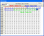
I will use your teminology of "Bank" for some space in EEPROM as one segment of data which have 5 ADC values organized in 10 bytes.


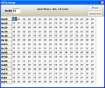
PIC16F877A EEPROM Space (256bytes total) :

PIC16F877A EEPROM Size 256 Bytes.jpg


Example :

PIC16F877A EEPROM.jpg


Bank1 starting address : 0x00 and have ADC value 712 on all 5 places.
Bank2 starting address : 0x0A and have ADC value 1012 on all 5 places.
Bank3 starting address : 0x14 and have ADC value 415 on all 5 places.
.
.
.


If you want to read or write some bank, lets say Bank2, you know that starting address for that bank is 0x0A and next 10 bytes you read or write only for Bank2.


Best regards,
Peter
 

Status
Not open for further replies.

Similar threads

Part and Inventory Search

Welcome to EDABoard.com

Sponsor

Back
Top