Continue to Site

Welcome to EDAboard.com

Welcome to our site! EDAboard.com is an international Electronics Discussion Forum focused on EDA software, circuits, schematics, books, theory, papers, asic, pld, 8051, DSP, Network, RF, Analog Design, PCB, Service Manuals... and a whole lot more! To participate you need to register. Registration is free. Click here to register now.

Digital Filter FIR using VHDL

Status
Not open for further replies.

ireon

Junior Member level 2
Joined
Mar 28, 2013
Messages
21
Helped
1
Reputation
2
Reaction score
1
Trophy points
1,283
Activity points
1,455
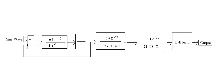
I should design a digital filter. I have coefficients values and I should write the VHDL code. I must implement the following circuit:

FIR_filter.gif


How can I describe it with the VHDL? I thought to use a for generate statement, but I don't manage to write the circuit. Someone could help me?
 

You can create array that holds the coefficients values. Coefficient values needs to be integer type, so u have to scale them by multiplication with 2**X.
example: 0.074 * 2^8 = 18.94 ~ 19 = 00010011
then there is need to calculate number of protection bits in order not to overflow the output ( as i recall it could be log2( sum of known coefficients (real ones not scaled))
Z-1 equals to D-flip flop, so the design simply contains only DFF and mul commands. The only fact that i dont like here is that u have to implement not transponded FIR filter which is poor for FPGA for big filter depths ( to get high speed there is need to create tree of sum).

simple code (with prolly some error as i dont have time to test it)


Code VHDL - [expand]
1
2
3
4
5
6
7
8
9
10
11
12
13
14
15
16
17
18
19
20
21
22
23
24
25
26
27
28
29
30
31
32
33
34
35
36
37
38
39
40
41
42
43
44
45
46
47
48
49
50
51
52
53
54
55
56
57
58
59
60
61
62
63
64
65
66
67
68
69
70
71
72
73
74
75
76
77
78
79
80
81
82
83
84
85
86
87
88
89
90
91
92
93
94
95
96
97
98
99
100
101
102
103
104
105
106
107
108
109
110
111
112
113
114
115
116
117
118
119
120
121
122
123
124
125
126
127
--------------------------------------------------------------------------------
--! @file FIR_EDABOARD.vhd
--! @brief SIMPLE FIR
--! poor implementation version 
--! @author Axcdd
--! @date 2013.06.19
--------------------------------------------------------------------------------
 
 
--! COMPONENTS and ARRAY PACKAGE
 
library ieee;
use ieee.std_logic_1164.all;
use ieee.numeric_std.all;
 
entity DFF is
    generic (
      N : natural := 8 --! DATA_WIDTH;
    );
    port (
      CLK : in std_logic; --! clock signal
      RESET : in std_logic; --! asynchronize reset signal
      DIN : in signed(N-1 downto 0); --! input
      DOUT : out signed(N-1 downto 0) --! output
    );
end entity DFF;
    
architecture behave of DFF is
  
begin
  
  p0:process(CLK,RESET)
  begin
    --! asynchronize reset
    if RESET='1' then
      DOUT <= (others=>'0');
    elsif rising_edge(CLK) then
      DOUT <= DIN;
    end if;
  end process p0;
  
end architecture behave;
 
 
library ieee;
use ieee.std_logic_1164.all;
use ieee.numeric_std.all;
 
PACKAGE array_coefficient IS
  TYPE coefficient IS ARRAY(natural range <>) OF integer;
  
  component DFF is
    generic (
      N : natural := 8 --! DATA_WIDTH;
    );
    port (
      CLK : in std_logic; --! clock signal
      RESET : in std_logic; --! synchronize reset signal
      DIN : in signed(N-1 downto 0); --! input
      DOUT : out signed(N-1 downto 0) --! output
    );
    end component DFF;
    
END array_coefficient;


library ieee;
use ieee.std_logic_1164.all;
use ieee.numeric_std.all;
use work.array_coefficient.all;
 
 
entity FIR_EDABOARD is
  generic (
    N  : natural := 8;  --! DATA_WIDTH
    L  : natural := 26 ;  --! FIR DEEPTH
    W  : natural :=8;    --! coefficient  scalar (c * 2**W to make them integer)
    G  : natural :=2;  --! additional protection bits
    COE : coefficient  --! array of integer coefficients
  );
  port (
    CLK  : in std_logic;  --! FIR clk
    RESET  : in  std_logic;  --! asynchronize reset
    DIN  : in std_logic_vector(N-1 downto 0);  --! input
    DOUT  : out std_logic_vector(N-1 downto 0)  --! output
  );
end entity FIR_EDABOARD;
 
architecture ARCH_FIR of FIR_EDABOARD is
 
  type CON is array (0 to L-1) of signed(N-1 downto 0);
    signal QA : CON;  --! connections between DFF
 
  type CON1 is array (0 to L-2) of signed(N+W-1 downto 0);
    signal MUL : CON1; --! DFF outputs after MULTIPLY with coefficients
    
  begin
 
  -------------------------Z-1 part-------------------------  
   
  stage1: DFF generic map (N) port map (CLK, RESET, signed(DIN), QA(0)); --! input buffor not shown in picture
   
  g0:for i in 0 to L-2 generate
    Zminus1: DFF generic map (N) port map(CLK,RESET,QA(i),QA(i+1));
  end generate g0;
 
  ---------------MULTIPLICATION-----------------------------
  g1:for i in 0 to L-1 generate
    MULTIPLY: MUL(i) <= QA(i) * to_signed(COE(i),W); 
  end generate g1;
 
  ----------------OUTPUT-----------------------------------
  
  p0: process(MUL)
  variable temp: signed(N+W+G-1 downto 0);
  begin 
    --! sum of MUL
    temp := (others=>'0');
    for i in 0 to MUL'length-1 loop
      temp := temp + MUL(i);
    end loop;
    --! DOUT after dropping ',' bits.
    DOUT <= std_logic_vector(temp(N+W+G-1 downto W+G));
  end process p0;
  
end architecture ARCH_FIR;

 
Last edited:

OK, anyway I created a structural description of the circuit using the for generate statement:

Code:
library IEEE;
use IEEE.STD_LOGIC_1164.ALL;

entity filtro_fir is 
          port(clock,reset: in std_logic;
			      input: in std_logic_vector(15 downto 0);
					output: out std_logic_vector(25 downto 0)
					);
			      
end filtro_fir;

architecture Structural of filtro_fir is

component shift 
         port(clock, reset: in std_logic;
			     input: in std_logic_vector(15 downto 0);
				  output: out std_logic_vector(15 downto 0)
				  );
end component;

component multipleier
         port(input: in std_logic_vector(15 downto 0);
			     h: in std_logic_vector(9 downto 0);
			     output: out std_logic_vector(25 downto 0)
				  );
end component;

component adder
         port(input_1,input_2: in std_logic_vector(25 downto 0);
		        output: out std_logic_vector(25 downto 0)
				  );
end component;

type h_vector is array(0 to 8) of std_logic_vector(9 downto 0);

signal h: h_vector := (

8 => "0000000100",
0 => "0000001011",
1 => "0000011111",
2 => "0000110100",
3 => "0000111101",
4 => "0000110100",
5 => "0000011111",
6 => "0000001011",
7 => "0000000100");

type segnale_1 is array(0 to 8) of std_logic_vector(15 downto 0);
signal s1: segnale_1;

type segnale_2 is array(0 to 8) of std_logic_vector(25 downto 0);
signal s2: segnale_2;

type segnale_3 is array(0 to 8) of std_logic_vector(25 downto 0);
signal s3: segnale_3;


begin
s1(0)<=input;
U0: multipleier port map(input=>s1(0),h=>h(8),output=>s3(0));
filter_gen: for i in 0 to 7 generate
U1:shift port map(clock=>clock,reset=>reset,input=>s1(i),output=>s1(i+1));
U2:multipleier port map(input=>s1(i+1),h=>h(i),output=>s2(i));
U3:adder port map(input_1=>s3(i),input_2=>s2(i),output=>s3(i+1));
end generate;

output<=s3(8);

end Structural;

Code:
library IEEE;
use IEEE.STD_LOGIC_1164.ALL;

entity FF_D is
            port (D,CLK,RESET: in std_logic;
                  Q: out std_logic);
end FF_D;

architecture behavioral of FF_D is

begin
             process (CLK,RESET)
begin
                     if RESET='1' then
							
							Q <= '0';
                     elsif (CLK'event and CLK='1') then
                     Q <= D;
                     
							end if;

             end process;

end behavioral;

Code:
library IEEE;
use IEEE.STD_LOGIC_1164.ALL;

entity shift is
         port(clock, reset: in std_logic;
			         input: in std_logic_vector(15 downto 0);
						output: out std_logic_vector(15 downto 0)
						);
end shift;
						
architecture Structural of shift is

component FF_D
          port(D,CLK,RESET: in std_logic;
                  Q: out std_logic);
end component;
						
begin

shift_gen: for i in 0 to 15 generate
U_shift: FF_D port map(clk=>clock,reset=>reset,D=>input(i),Q=>output(i));
end generate;

end Structural;


Code:
library IEEE;
use IEEE.STD_LOGIC_1164.ALL;
use IEEE.STD_LOGIC_SIGNED.ALL;

entity multipleier is
         port(input: in std_logic_vector(15 downto 0);
			     h: in std_logic_vector(9 downto 0);
			     output: out std_logic_vector(25 downto 0)
				  );

end multipleier;

architecture Behavioral of multipleier is

begin

output<=input*h;

end Behavioral;

Code:
library IEEE;
use IEEE.STD_LOGIC_1164.ALL;
use IEEE.STD_LOGIC_SIGNED.ALL;

entity adder is
       port(input_1,input_2: in std_logic_vector(25 downto 0);
		      output: out std_logic_vector(25 downto 0)
				);
end adder;

architecture Behavioral of adder is

begin

output<=input_1+input_2;

end Behavioral;

The circuit has been generated but I have a warning message: "Using initial value ("0000001011","0000011111","0000110100","0000111101","0000110100","0000011111","0000001011","0000000100","0000000100") for h since it is never assigned". What is the problem? I created the new type assigning the h values with the for generate. The filter has 16 bit input and 9 coefficients.
 

Its not a problem. H is only given an initial value, so it is effectively a constant. If you dont assign a signal a value during runtime you will get this warning.
 

Ok. I executed a Test Bench and the circuit works perfectly.
 

I should design a digital filter of first order ADC Sigma-Delta converter with 8 bits, an over sampling ratio of 64 (OSR = 64),and sampling frequency of 10.24MHz.I make it with MAtLAB SIMULINK as shown in this figure:


Can somone help me by giving a vhdl Code of this filter because i must implement it.

Thanks for help
 

I should design
....

Can somone help me by giving a vhdl Code of this filter because i must implement it.

Thanks for help


I think the clue is that you should do the work, not someone else.
 

Status
Not open for further replies.

Similar threads

Part and Inventory Search

Welcome to EDABoard.com

Sponsor

Back
Top