Continue to Site

Welcome to EDAboard.com

Welcome to our site! EDAboard.com is an international Electronics Discussion Forum focused on EDA software, circuits, schematics, books, theory, papers, asic, pld, 8051, DSP, Network, RF, Analog Design, PCB, Service Manuals... and a whole lot more! To participate you need to register. Registration is free. Click here to register now.

apr9600 power supply

Status
Not open for further replies.

khangzing

Full Member level 2
Joined
Feb 22, 2013
Messages
123
Helped
3
Reputation
6
Reaction score
3
Trophy points
1,298
Activity points
2,148
in the data sheet it mention pin 16 of apr9600 has to be connect by analog power supply and pin 28 should connect by digital power supply,that mean i need 2 kinds of battery?? so weird!! please, anyone know how to do it...urgent...
 

VCCA pin should be connected to Vcc as shown in datasheet page 9. It is the supply for analog circuit inside the chip like microphone preamplifier, amplifier for speaker, etc...
 

So if I using dc example battery, it should be ok right?
 

ok thanks. for the sensor part,i couldn't get the desire waveform, and it seem doesn't work at all, the connection all i had check and seem ok,the code i had mail you,which use to modulate the ir signal to 38khz, the voltage i had measure through the emitter is 1.5v with 68 ohm and 28 ohm. And 1 more thing is, the pic16f877a pin 1 should connect to power supply with 1 10k pull up resistor right?it need to connect to ground? or connect a 10k resistor then 0.1uf capacitor then ground?
 

Post screenshot of circuit. Pin 1 should connect to Vcc through a 10K resistor if Pin 1 is MCLR.

This mikroC Code will generate 38 KHz square wave at RB0 pin. Clock should be 8 MHz.


Code C - [expand]
1
2
3
4
5
6
7
8
9
10
11
12
13
14
15
16
17
18
//Timer0
//Prescaler 1:1; TMR0 Preload = 46; Actual Interrupt Time : 26.375 us
 
//Place/Copy this part in declaration section
void InitTimer0(){
  OPTION_REG     = 0x88;
  TMR0       = 46;
  INTCON     = 0xA0;
}
 
void Interrupt(){
  if (TMR0IF_bit){ 
    TMR0IF_bit = 0;
    TMR0 = 46;
    PORTB.F0 = ~PORTB.F0
 
  }
}

 
Last edited:

i'm using 20Mhz crystal and i'm using MPLAB
 

This is for PIC16F, 20 MHz.


Code C - [expand]
1
2
3
4
5
6
7
8
9
10
11
12
13
14
15
16
17
//Timer0
//Prescaler 1:4; TMR0 Preload = 122; Actual Interrupt Time : 26.3 us
 
//Place/Copy this part in declaration section
void InitTimer0(){
  OPTION_REG     = 0x81;
  TMR0       = 122;
  INTCON     = 0xA0;
}
 
void interrupt(){
  if (INTCONbits.TMR0IF){ 
    INTCONbits.TMR0IF    = 0;
    TMR0         = 122;
    PORTBbits.RB0 = ~PORTBbits.RB0
  }
}


where you get this?as per datasheet,i don't understand how to set it and even this also i couldn't understand...can u explain how it works?
 

Just change the PORTBbits.RB0 to whatever pin the IR led is connected to. IR led will be fed with 38 KHz pulses.

F = 38 KHz, T = 1/F = 26.3 us. Timer toggles RB0 pin every 26.3 us.

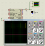
92016d1370449676-ir.png
 

Attachments

  • ir.png
    ir.png
    130.6 KB · Views: 100
Last edited:

will this code work in MPLAB?D1 is the emitter?

- - - Updated - - -

i want to know how this code working.....
 

Yes. It is MPLAB C18 or Hi-Tech C Code. Also works with XC8. D1 is IR led. 38 KHz square wave is applied to IR LED. Most microcontroller pins can source or sink only 25 mA. You need to use a transistor switching circuit driven by MCU and transistor will drive the IR led. Your IR leds max current rating is 100 mA, So, you have to work it at 50 or 75 mA.
 

i'm using high-tech universal toolsuite,is that compatible?and it should generate about 76-78khz and divide by 2 or 38khz?the transistor switching circuit how to connect?got no idea....
 

The hi-tech universal toolsuite is compatible. Yes, the interrupt routine should give you around 78 kHz frequency with 20MHz crystal (1:256 prescaler value). You'll have to delay each clock in software to get the 38kHz freqeuncy you need.

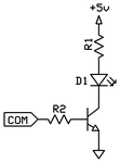
The switch transistor is easy to connect. Check the schematic I attached to this post.
D1 is the IR LED.
R1 is the current limiting resistor for the IR led. For 100mA at 3V with a 5V supply you should use a 22 Ohm resistor (around 90mA); it will keep the IR at a very high intensity yet not at maximum intensity (which would break the IR LED in very short time). Even better, you could use a 27 Ohm resistor (74mA), still very high intensisty but longer lifetime.
the COM label is the PIC output. The resistor R2 is to limit the current on the transistor base. You have to calculate it based on the transistor Beta value to get the right current you need.
The transistor is an NPN, and it has to be a fast commutation transistor, otherwise it might be unable to properly switch at the 38kHz frequency. Now, I haven't checked the datasheet but is that 38khZ frequency the only one you can use or is it the maximum frequency? I ask this because with an 8MHz crystal and 1:256 prescaler value on timer, you'd get a 31250Hz frequency, without delaying anything in software, it's faster and easier. Check if you can approach this way.
 

where is the schematic u attached? the receiver work with 38khz,so i need to have 38khz of carrier signal, i'm using 20Mhz crystal. what is 1:256 mean actually?
 

Oh, I'm very sorry about that, I wrote the message and forgot to attach it as I was in a hurry. I'm attaching it right now.
 

Attachments

  • switch_trans.png
    switch_trans.png
    3.9 KB · Views: 60

what is 1:256 mean? how u calculate the voltage? which transistor brand is better in this case?

and for the resistor R2 u said i have to calculate based on the transistor Beta value to get the right current i need....how...?sorry-.-
 

For the transistor I would suggest you searching the forum for a few explanations. There is a recent thread of mine I suggest you to read:
https://www.edaboard.com/threads/288943/
Read reply #2 for the current calculation, and reply #7 for a website with a lot of transistors (look at the small signal transistors page). Basically, you have to calculate the curren on the Collector of the transistor like this:
Ic = Ib*hfe
where Ib is the current on the transistor base (coming from the PIC) and hfe is the Beta of the transistor. By applying Ohm's law on the resistor R2 you can calculate how much current you'll be sending on the transistor base (I=V/R) so you'll know how much current will flow through the transistor Collector.

The 1:256 above is the prescaler value that you must set in your PIC Timer's prescaler settings (PS2, PS1, PS0). It will trigger a Timer interrupt every MainClock/256.
 

for voltage go through IR LED,how to calculate? (R=V/I) if i want to get 1.6v and 50mA to drive my IR LED?
for the APR9600, during recording time,do i need to connect the particular pin to the ground?for example i want to record voice into pin 1, in the datasheet mention i need to apply make it low level,it mean it connect to ground and make it high mean connect to +5v? low mean connect to ground? i tried to do that but my circuit seem doesn't work,i can't hear the beep sound and the light of LED doesn't light up as well... for parallel connection of copper strip board(example pin 16 of apr9600), i had connected 1 of the pin of 0.1uf and 22uf capacitor in series with the pin 16(only 1 of the pin which is in the same trace of copper) is that consider parallel?

and for the sensor part,the problem is because i didn't connect a transistor to drive the IR emitter?after i connect should be ok?

- - - Updated - - -

so is that the Ib i should get is max 25 mA?
 

For the voltage on the IR diode you only need to calculate the proper R1 resistor:
Vm= main spupply voltage = 5V
Vd = Voltage on diode = 1.6V
Ad = current on diode = 50mA = 0.050A

R1 = (Vm - Vd)/Ad = (5 - 1.6)/0.050 = 68 Ohm

Yes, the problem of the IR sensor is because the PIC may drive components up to only a few mA, 25mA on most PICs. Your IR diode is rated 100mA so at half of that current should be given for it to work nicely. At 25mA it would merely start lighting. With a transistor you can increase the current as much as you need.

For series and parallel, i though you at least knew what they are and how to do it.. if not please search the elementary questions forum, I'm sure there is something about it.

Yes, putting the pin low or high means (respectively) GND or 0V, and 5V (TTL level) or 3.3V (MOS level). In your case, GND and 5V.
 

Status
Not open for further replies.

Similar threads

Part and Inventory Search

Welcome to EDABoard.com

Sponsor

Back
Top