ali kotb
Member level 3
hello ,
I found difficulty in proving the transient response of continuous time amplifier
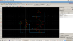
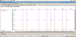
attached is the veriloga code , the test bench , and the o/p transient
the transient is differential with no feedback (as OTA) , but when applying the input and fb capacitance , the o/p is no longer differential
please help me
`include "discipline.h"
`include "constants.h"
// model opamp - Non Ideal OpAmp Model
module opamp (voutp,voutn, vin_p, vin_n, vspply_p, vspply_n, vcm );
input vin_p , vin_n , vcm;
inout vspply_p, vspply_n;
output voutp,voutn ;
electrical vin_p, vin_n, voutp, voutn, vspply_p, vspply_n, vcm;
parameter real gain = 1412.5 exclude 0.0;
parameter real pole_freq = 172k;
parameter real rin = 12.0M exclude 0.0;
parameter real rout = 75.0;
parameter real ibias = 0.0n;
parameter real vin_offset = 0.0u;
// parameter real slewp = 20.0M from (0:inf);
// parameter real slewn = -20.0M from (-inf:0);
real c1, r1;
real r_rout,gm_nom, vin_val;
electrical coutp, coutn, vref;
analog
begin
@(initial_step)// or initial_step("dc", "ac", "tran", "xf"))
begin
gm_nom = 1.0;
r1 = gain/gm_nom;
c1 = gm_nom/(`M_TWO_PI * pole_freq * gain);
r_rout = rout;
end
vin_val= V(vin_p, vin_n) + vin_offset;
// ------ Vref is at Virtual Ground
V(vref,vspply_n) <+ 0.5*V(vspply_p,vspply_n);
// ------ Input Stage
I(vin_p, vin_n) <+ vin_val / rin;
I(vref, vin_p) <+ ibias;
I(vref, vin_n) <+ ibias;
// ------ GM stage
I(vcm, coutp) <+ (gm_nom/2)*vin_val ;
I(vcm, coutn) <+ -(gm_nom/2)*vin_val ;
// ------ Dominant Pole.
I(coutp, vcm) <+c1*ddt(V(coutp, vcm));
I(coutp, vcm) <+ V(coutp, vcm)/r1;
I(coutn,vcm) <+ c1*ddt(V(coutn, vcm));
I(coutn, vcm) <+ V(coutn, vcm)/r1;
// ------ Output Stage.
I(vcm, voutp) <+ (V(coutp) - (vcm))/r_rout;
I(voutp, vcm) <+ V(voutp, vcm)/r_rout;
I(vcm, voutn) <+ (V(coutn) - V(vcm))/r_rout;
I(voutn, vcm) <+ V(voutn, vcm)/r_rout;
end
endmodule
I found difficulty in proving the transient response of continuous time amplifier
attached is the veriloga code , the test bench , and the o/p transient
the transient is differential with no feedback (as OTA) , but when applying the input and fb capacitance , the o/p is no longer differential
please help me
`include "discipline.h"
`include "constants.h"
// model opamp - Non Ideal OpAmp Model
module opamp (voutp,voutn, vin_p, vin_n, vspply_p, vspply_n, vcm );
input vin_p , vin_n , vcm;
inout vspply_p, vspply_n;
output voutp,voutn ;
electrical vin_p, vin_n, voutp, voutn, vspply_p, vspply_n, vcm;
parameter real gain = 1412.5 exclude 0.0;
parameter real pole_freq = 172k;
parameter real rin = 12.0M exclude 0.0;
parameter real rout = 75.0;
parameter real ibias = 0.0n;
parameter real vin_offset = 0.0u;
// parameter real slewp = 20.0M from (0:inf);
// parameter real slewn = -20.0M from (-inf:0);
real c1, r1;
real r_rout,gm_nom, vin_val;
electrical coutp, coutn, vref;
analog
begin
@(initial_step)// or initial_step("dc", "ac", "tran", "xf"))
begin
gm_nom = 1.0;
r1 = gain/gm_nom;
c1 = gm_nom/(`M_TWO_PI * pole_freq * gain);
r_rout = rout;
end
vin_val= V(vin_p, vin_n) + vin_offset;
// ------ Vref is at Virtual Ground
V(vref,vspply_n) <+ 0.5*V(vspply_p,vspply_n);
// ------ Input Stage
I(vin_p, vin_n) <+ vin_val / rin;
I(vref, vin_p) <+ ibias;
I(vref, vin_n) <+ ibias;
// ------ GM stage
I(vcm, coutp) <+ (gm_nom/2)*vin_val ;
I(vcm, coutn) <+ -(gm_nom/2)*vin_val ;
// ------ Dominant Pole.
I(coutp, vcm) <+c1*ddt(V(coutp, vcm));
I(coutp, vcm) <+ V(coutp, vcm)/r1;
I(coutn,vcm) <+ c1*ddt(V(coutn, vcm));
I(coutn, vcm) <+ V(coutn, vcm)/r1;
// ------ Output Stage.
I(vcm, voutp) <+ (V(coutp) - (vcm))/r_rout;
I(voutp, vcm) <+ V(voutp, vcm)/r_rout;
I(vcm, voutn) <+ (V(coutn) - V(vcm))/r_rout;
I(voutn, vcm) <+ V(voutn, vcm)/r_rout;
end
endmodule