paulfjujo
Advanced Member level 4
- Joined
- Jun 9, 2008
- Messages
- 1,464
- Helped
- 298
- Reputation
- 596
- Reaction score
- 283
- Trophy points
- 1,363
- Location
- France 01800
- Activity points
- 10,544
Hello,
Here is a project of Frequency Generator with good performances for Hobbies application,
or more ... if you need more accurate , buy Professional Instrument !
Use a PIC18F46K22 because it has a big ROM and RAM memory !
and can run at 40MHZ (Q=10Mhz*PLL) -> 1 cycle within 100nS and 27 cycles to build DDS output !
so, one DDS Generator output is made by the PIC
in the range 1Hz .. 25 000Hz so BF range (even it can goes up to 40Khz)
with a choice of 6 different shapes of signal :
SINUS,SQUARE,TRIANGLE,SAW, rev SAW, RECT
RECT is particular, because adjust of Duty cycle from 1% to 99% is possible
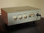
An amplifier is used to have a low impedance output
Output Amplitude is 1,8V eff on load as low as 82 ohms
The second DDS , is made by a special dedicated circuit : AD9850 (mounted on a breakboard)
and driven, only during the time to set the Frequency value .
Output is SINUS ( and SQUARE if you need it )
from the range 1Hz ... to 40.000.000 Hz (40Mhz)
nota: 0.1Hz can be possible ...
so it's cover BF and HF range.
Output is amplified , because too low level,
so amplifier can deliver 1,5V eff on load as low as 50 ohms !
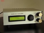
Human interface is made by a LCD 2 lines of 16 car, and a Joystick to choose items in a Menu
and make Frequencey value adjustement...
The second DDS AD980 is a special item of the menu.
Except during modification in the Menu or AD9850 frequency adjustement
BOTH outputs are delivering a signal.
This generator was designed mainly for Vintage Radio repairing.
PO,GO,OC, MF, alignement...
Both DDS can be driven also , by a RS232 terminal , or external programme to fix
the shape or frequency value..
Example is done by using Vbray Terminal
Both interface LCD+Joystick and RS232 terminal are redondant...
All details on my web page ..
included program source (C18) ,schematic and explanations ..
sorry, in French only !
don't ask to translate it !
Here is a project of Frequency Generator with good performances for Hobbies application,
or more ... if you need more accurate , buy Professional Instrument !
Use a PIC18F46K22 because it has a big ROM and RAM memory !
and can run at 40MHZ (Q=10Mhz*PLL) -> 1 cycle within 100nS and 27 cycles to build DDS output !
so, one DDS Generator output is made by the PIC
in the range 1Hz .. 25 000Hz so BF range (even it can goes up to 40Khz)
with a choice of 6 different shapes of signal :
SINUS,SQUARE,TRIANGLE,SAW, rev SAW, RECT
RECT is particular, because adjust of Duty cycle from 1% to 99% is possible
An amplifier is used to have a low impedance output
Output Amplitude is 1,8V eff on load as low as 82 ohms
The second DDS , is made by a special dedicated circuit : AD9850 (mounted on a breakboard)
and driven, only during the time to set the Frequency value .
Output is SINUS ( and SQUARE if you need it )
from the range 1Hz ... to 40.000.000 Hz (40Mhz)
nota: 0.1Hz can be possible ...
so it's cover BF and HF range.
Output is amplified , because too low level,
so amplifier can deliver 1,5V eff on load as low as 50 ohms !
Human interface is made by a LCD 2 lines of 16 car, and a Joystick to choose items in a Menu
and make Frequencey value adjustement...
The second DDS AD980 is a special item of the menu.
Except during modification in the Menu or AD9850 frequency adjustement
BOTH outputs are delivering a signal.
This generator was designed mainly for Vintage Radio repairing.
PO,GO,OC, MF, alignement...
Both DDS can be driven also , by a RS232 terminal , or external programme to fix
the shape or frequency value..
Example is done by using Vbray Terminal
Both interface LCD+Joystick and RS232 terminal are redondant...
All details on my web page ..
included program source (C18) ,schematic and explanations ..
sorry, in French only !
don't ask to translate it !