Continue to Site

Welcome to EDAboard.com

Welcome to our site! EDAboard.com is an international Electronics Discussion Forum focused on EDA software, circuits, schematics, books, theory, papers, asic, pld, 8051, DSP, Network, RF, Analog Design, PCB, Service Manuals... and a whole lot more! To participate you need to register. Registration is free. Click here to register now.

non inverting amplifier

Status
Not open for further replies.

ant17

Member level 2
Joined
May 20, 2013
Messages
47
Helped
0
Reputation
0
Reaction score
0
Trophy points
1,286
Activity points
1,627
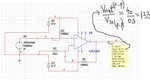
hi guys i have a lm741 powered by two 9 volt batteries to give me a dual power supply the input connected to a colpits oscillator giving 300mv peak to peak the the feedback resistor from pin 6 to 2 then to negative 100k and 1k but at the output i only get 100mv peak to peak the frequency is 166khz does any body have an idea what i might be doing wrong the oscilloscope is measure between negative and the output pin
 

feedback resistor from pin 6 to 2 then to negative 100k and 1k
I hope you mean 100K from pin 6 to pin 2, and 1K from pin 2 to the midpoint between the batteries. Also, the input should be DC biased to the midpoint between the batteries as well.

Aside from that the LM741 is very slow, so it's not good for amplification at high frequencies.
 

hi guys thanks for your replys i wil try a to send a schematic a little bit later
 

hi guys i was unable generate a schematic of my circuit but from whats been said i should have on batteries 0ne postive lead the negative goes to the postive of second battery clip and then i will have a negative and positive supply but i should be taking so called ground connections from the mid point between the two battery clips which is possitive and negative stuck together
 

i should be taking so called ground connections from the mid point between the two battery clips which is possitive and negative stuck together
Yes, that's right.
 

....the frequency is 166khz .....

The 741 type opamp has again of less than 10 at 166 kHz. More than that, the limited slew rate allows not more than some hundreds of mV (output) at that frequency.
 

my circuit.jpg
The 741 type op amp has again of less than 10 at 166 kHz. More than that, the limited slew rate allows not more than some hundreds of mV (output) at that frequency.

hi i attacched my circuit the colpits oscillator runs at 166khz yet the output waveform is square wave looking and i am not getting amplification and i don't understand i am roughly putting a 1 to 2 volts peak to peak with out any amplification also i forgot to put a the emitter resistance which is 1k
 

@ant17:in place of 741,try using an opamp with a faster slew rate and better gain at high-frequencies like TL3474
 

@ant17:in place of 741,try using an opamp with a faster slew rate and better gain at high-frequencies like TL3474

in my circiuit drawing attached to my last post i used a ca3130 opamp but still know sucess
 

You need DC bias for the +input of the opamp. A 100K resistor between the +input and ground should work.
 

You need DC bias for the +input of the opamp. A 100K resistor between the +input and ground should work.

Yes - and, more than that, where is the ground node?
 

yes the ground node is between the two 9volt batteries

hi to check if my problems with my op amp are because of frequency so i tryed it at 8khz and found there to be a gain of 3 or 4 and the op amp is a Ca3130 would frequency response be the problem do you think:-(
 

Have you fixed the bias? See post 11.
 

Have you fixed the bias? See post 11.

i connected a 100k from the positive pin + but still no amplification even at much lower frequencies using ca3130
 

Maybe it's clipping. What are the amplitudes of the input and output signals? Is the DC voltage at the output close to ground with no input, or is it close to + or -9V? Van you show the circuit you're using now?
 

Maybe it's clipping. What are the amplitudes of the input and output signals? Is the DC voltage at the output close to ground with no input, or is it close to + or -9V? Van you show the circuit you're using now?

no its only about 1 to 2volts peak to peak does anybody have a working schematic of a high gain non inverting amplfier that i could try that they know works so i can find out whats wrong

- - - Updated - - -

Maybe it's clipping. What are the amplitudes of the input and output signals? Is the DC voltage at the output close to ground with no input, or is it close to + or -9V? Van you show the circuit you're using now?

no its only about 1 to 2volts peak to peak does anybody have a working schematic of a high gain non inverting amplfier that i could try that they know works so i can find out whats wrong
 

does anybody have a working schematic of a high gain non inverting amplfier that i could try that they know works so i can find out whats wrong

Do u need schematic of non-inverting amplifier along with colpitts oscillator???
attached is a high-gain non-inverting amplifier
 

Attachments

  • Capture.JPG
    Capture.JPG
    107.4 KB · Views: 68

Status
Not open for further replies.

Similar threads

Part and Inventory Search

Welcome to EDABoard.com

Sponsor

Back
Top