Continue to Site

Welcome to EDAboard.com

Welcome to our site! EDAboard.com is an international Electronics Discussion Forum focused on EDA software, circuits, schematics, books, theory, papers, asic, pld, 8051, DSP, Network, RF, Analog Design, PCB, Service Manuals... and a whole lot more! To participate you need to register. Registration is free. Click here to register now.

[SOLVED] Voltage controlled DC sweep

Status
Not open for further replies.

abuhafss

Full Member level 2
Joined
Aug 8, 2010
Messages
136
Helped
1
Reputation
2
Reaction score
0
Trophy points
1,296
Activity points
2,346
Hi

I have a requirement to have a DC sweep from 5v-30v depending upon input voltage.

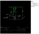
Please see the diagram. The control circuit will have 2 inputs i.e. 9v (ON) OR ZERO (OFF). When 9V, the control circuit will provide a DC sweep from 5V to 30V. Before reaching 30V the input will receive ZERO from some other module hence the sweep should stop and the voltage at the output should standstill.

For example, when the control circuit receives ZERO volts at the input, the voltage at the output was 10.6V. The sweep should stop but the voltage at the output remains constant at 10.6V until the system is reset.

I shall appreciate if someone can guide me some solution. The sweep period is not very important but of course, should not be very slow.


Attachments

  • 30V SWEEP.gif
    30V SWEEP.gif
    5.2 KB · Views: 81

There are many ways to implement a slow ramp. Rate, linearity and how close to the supply rails, impedance or drive current and methods to control are important to know first if anything is important.
 

Thanks for your response.

I am sorry, I cannot understand the terms.
I simply want a control circuit which could supply 5 - 30v within 5-10 sec.
No other factors are important.
 

There are many ways to skin a cat;
the way I would do it:

A Microcontroller which would detect your 0 or 9 volt input (via a voltage divider), then proceed to drive the DAC to sweep according to your requirements. The DAC output will be a ramp of 0 to 5 volt, which you then amplify with a high voltage op amp to 30 volts. The OPA551 would be such an opamp, there are many others.

- - - Updated - - -

Thanks for your response. But I don't want to use a micro-controller.
 

Thanks for your response. But I don't want to use a micro-controller.
You previously said no other factors are important and now you give us a new restriction. Any others we should know about so we can avoid spinning our wheels?
 

Sorry for my incomplete information.

My requirement is simply a transistor based or 555 based or Op amp based ramp generator.

Ramp should be 5v - 30v and the circuit should have a pause option.
 

What signal will reset the output to 5V?

How long do you need to hold the signal after the ramp is stopped? To what accuracy?
 

Actually, I need only a single ramp wave.
Once the ramp his hold for 2-3 seconds, the whole system will be reset which will also initialize the ramp to be triggered.

By the way, I have got a transistor based generator which suits my need.
When the switch is opened the ramp is paused.
However, the ramp starts from zero volts.
I want to modify it such that in idle state the voltage at the output is constantly 5V.
 

Attachments

  • Ramp Generator.gif
    Ramp Generator.gif
    5.7 KB · Views: 83

That circuit is a relaxation oscillator that generates an exponential ramp. Is that OK or would you prefer a linear ramp?

Also how will you place that circuit in a hold mode as you desired?

I am working on a circuit using an op amp integrator that generates a linear ramp with a hold. I'll try to post that tomorrow, if nothing else comes up.
 

A current source into a capacitor provides this ramp. The cap needs a switch to reset the charge and the current source needs a switch to enable. The output can be buffered with a low input bias FET op Amp. A FET can provide the current source. Can you figure it out from there? The cap should have low memory so a film cap is best if you need high accuracy.

You could also use a DAC with a counter input.
 

That circuit is a relaxation oscillator that generates an exponential ramp. Is that OK or would you prefer a linear ramp?

Also how will you place that circuit in a hold mode as you desired?

I am working on a circuit using an op amp integrator that generates a linear ramp with a hold. I'll try to post that tomorrow, if nothing else comes up.


Really appreciate your help, thanks. I'll be waiting for your circuit.

In the meantime, the exponential ramp also working. When the switch is opened, the ramp will be paused.
As mentioned in my previous post, the only problem left is to have constant 5V until the ramp is triggered.
 

Here is my design for you.
two inputs HOLD and RESET are switches. (tidied up.)

Either Trailing edge of Reset initiates Start or trailing edge of HOLD ( after reset removed)

After you define the load, you can add a unity gain current buffer. You can use OpAmp or OA with emitter follower)

One easy way to change speed is to change the Cap value.

sweep.jpg
 

Attachments

  • sweep.jpg
    sweep.jpg
    87.4 KB · Views: 76
Last edited:

When the switch is opened on your (OP) circuit, the voltage drops to zero. It has no hold capability as configured.

Below is a circuit using an op amp integrator.

The op amp is a low offset, rail-rail type.

The N-Mosfets should be rated for at least 40V and have a low input capacitance (gate charge). M2 is to reset the integrator capacitor upon startup.

To increase the ramp time you can increase the value of R1 and/or C1.

C1 and C2 should be a film or ceramic cap for low leakage.


5-30V Ramp.gif
 
Last edited:

Thank you, both of you.

Both the designs are perfect.
Really appreciate your efforts.

Thanks once again.
 

M2 is to reset the integrator capacitor upon startup.

View attachment 91876

Hi Crutschow,

I have similar requirement i.e. pause-able DC ramp 5-24V and control voltage is 3V instead of 9V.

Instead of M2, if we short the integrator capacitor (momentarily) when switching on, will it work?

What will be the effects if C1 is electrolytic?
 
Last edited:

Status
Not open for further replies.

Part and Inventory Search

Welcome to EDABoard.com

Sponsor

Back
Top