Welcome to our site! EDAboard.com is an international Electronics Discussion Forum focused on EDA software, circuits, schematics, books, theory, papers, asic, pld, 8051, DSP, Network, RF, Analog Design, PCB, Service Manuals... and a whole lot more! To participate you need to register. Registration is free. Click here to register now.
If the output waveform shown above is the output of an optocoupler then you need to change the optocoupler only... For faster response, you should use high speed optocoupler like 6N137 & this is not a transistor. Its a photo transistor & there is a lot of different between these two.
Try to ask questions with full details (Clear circuit diagram, requirement, clear part number, etc..) & you can get more clear answers...
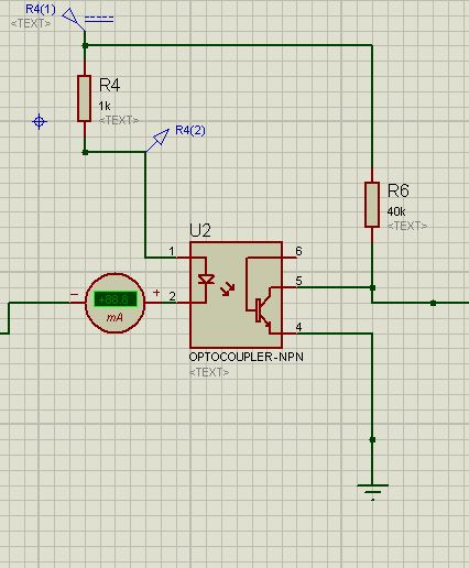
You can also significantly speed up the response of the opto-copupler by adding a resistor from the base connection to ground (suggest you try 4.7K to 10K) but it will also reduce the sensitivity. If you have enough LED current this isn't a problem.
The circuit doesn't show any power connections, but I assume there must be some! It is difficult to see the timebase of the waveforms but they seem incredibly slow, even for high resistors.
If the high voltage signal and the microcontroller share the same ground, you don't need an opto-isolator, just a resistive divider to reduce the voltage. You can place a small capacitor across the top resistor in the divider to speed up the response if you need to.
With the schematic that the original poster provided, the positive pulse that is applied to the optocoupler's anode is the the same as connected to optocoupler's collector.
This site uses cookies to help personalise content, tailor your experience and to keep you logged in if you register.
By continuing to use this site, you are consenting to our use of cookies.