Continue to Site

Welcome to EDAboard.com

Welcome to our site! EDAboard.com is an international Electronics Discussion Forum focused on EDA software, circuits, schematics, books, theory, papers, asic, pld, 8051, DSP, Network, RF, Analog Design, PCB, Service Manuals... and a whole lot more! To participate you need to register. Registration is free. Click here to register now.

Audio amplifier project

Status
Not open for further replies.

stelistul

Newbie level 4
Joined
May 20, 2013
Messages
7
Helped
0
Reputation
0
Reaction score
0
Trophy points
1,281
Activity points
1,326
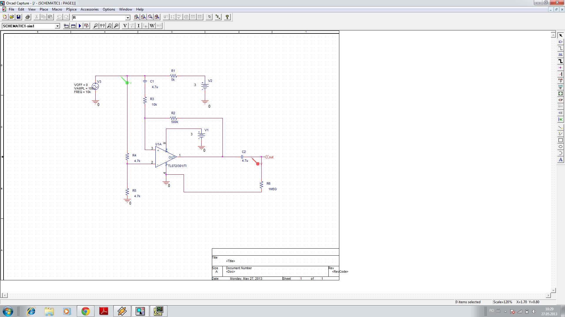
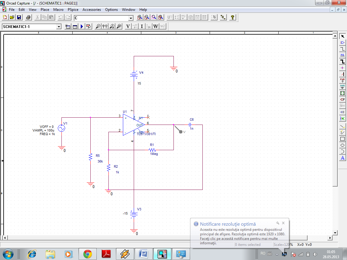
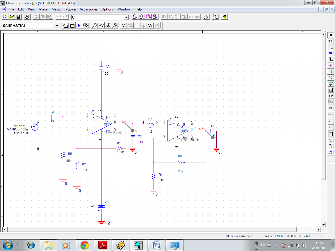
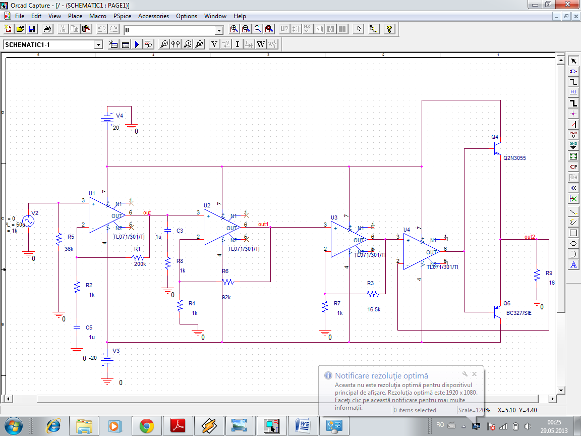
I'm student at electronics in second year and I have to do a project in orcad-an audio amplifier with input voltage 100uV, power 17W, 36k input resistance and load resistance 16 ohm.I tried several schemes but none went probably order that the input voltage is so low.Please can someone help me with a circuit and some pointers for a beginner?Thanks!
 

100uV, is very low, what you need to do is to build a low noise pre-amplifier with a gain of > 1000. So I would think two low noise opamps, the quietest one at the input with a gain of 30 -> 100. (depending on your bandwidth requirements). One you have a good level, say >50mV, better 200mV then a main amplifier can be used. Google for low noise preamps or opamps and make your choice.
Frank
 

But the problem is that almost all I find is with integrated circuit and I can't use it in Orcad for my project.
 

Are you sure the input voltage is 100uV, not 100mV? If so, Chuckey's suggestion is good - first a preamplifier to boost the voltage, then a power amplifier.

Presumably you need a volume control as well. If so, put that between the preamp and the power amp. If you put it at the input, it will degrade the noise performance.

What's the actual problem? If you are not allowed to use opamps, then just use discrete transistors.
 

Yes is 100uV.

- - - Updated - - -

I made this schem in Orcad for a pre amplifier but isn't going,I have 0 at out.TL072 is a low noise op amp no?I made some mistake?
 

  1. Your circuit has positive feedback instead of negative feedback.
  2. A TL072 can't work with such a low supply voltage. Anything from 12V to 30V would be good.
  3. If you use a single ended power supply, then you need to bias the input to half the supply voltage.
 

If the (+) and (-) inputs are swapped so that the opamp has negative feedback instead of positive feedback then the R4-R5 voltage divider is shorted to ground by the signal source because an input coupling capacitor is missing.
 

I made another preamp,what you say?it is ok?How do I calculate the output capacitor?
 

I made another preamp,what you say?it is ok?How do I calculate the output capacitor?
Much better! There's one problem that may not be obvious: The TL071 has a gain-bandwidth of about 3 MHz, so with a voltage gain of 1000 the frequency response of your amplifier will roll off above about 3KHz. This is not good - for audio we want the frequency response to reach at least 20KHz.

It will be much better if you change R1 to 100K. Then gain is 100 and frequency response goes up to 30KHz. Now there isn't enough gain so you need to add another opamp gain stage. I would set gain = 25 for the second stage. That will give 250mV output from the second stage for 100uV input to the first stage.

In between the first stage and second stage, you can put a 1uF coupling capacitor and a 50K potentiometer for the volume control. It's probably a good idea to put a 1uF coupling capacitor at the input to the first stage as well, before the 36K resistor.
 

why I need a capacitor at input if I don't have DC component?I had change the capacitor at 1u but I have a DC component at 1mV
 
Last edited:

I made this preamp how you say godfreyl.But now I need another amp stage for voltage.I can make it with another AO or just with transistors?whi is the sine deformed at begin?


why I need a capacitor at input if I don't have DC component?
You probably don't need it. It will only be useful if the input is connected to something with DC offset. Even then, it will only be a problem if the DC at the input is more than about 100mV.

You do need a capacitor between the output of the first opamp and the input of the second one because there will be DC offset at the output of the first opamp.

I made this preamp how you say godfreyl.
I think your brain was switched off when you drew that. Surely you know (or can find out) how to connect a volume control? Why are C1 and C2 connected to ground? Do you think it's a good idea to use a power supply voltage higher than the absolute maximum allowed for the opamp?

BTW, 24K is a standard resistor value. 25K is not. See here: https://en.wikipedia.org/wiki/Preferred_number#E_series

But now I need another amp stage for voltage.I can make it with another AO or just with transistors?
Think about this:
The amplifier has to give 17W output into a 16 Ohm load. So, what rms output voltage is required? What is the peak output voltage? What power supply voltage will be needed? How much current must be delivered to the load?

whi is the sine deformed at begin?
I don't know.
 

A TL071 oscillates at a high frequency when it tries to drive the capacitance of a shielded cable (about 200pF or more) and you have the outputs of the TL071 opamps shorted to ground with a 1uF capacitor.
 

I made a scheme but I don't know if is corect or I had made a lot of stupid....I don't know what is the rol of the last AO(buffer?),but if I don't put it at final my voltage is not amplified.Power suplly are calculated whith P=(E(square))/8Rs?
 

I don't know if is corect or I had made a lot of stupid....
The latter. Read my previous post again. Also look at the datasheets for the opamp and transistors you want to use. They contain important information you need.

Power suplly are calculated whith P=(E(square))/8Rs?
No, try again.

- - - Updated - - -

There's a nice list of transistors here, to help you choose. Click the links at the top of the page to see medium power and high power transistors.
 

1) Battery V3 is shown backwards.
2) The total supply is 40V but the maximum allowed supply for a TL071 is only 36V.
3) The output transistors are not biased so they will cause severe crossover distortion.
4) The total voltage gain is more than 327 THOUSAND which is ridiculous.
 

Status
Not open for further replies.

Part and Inventory Search

Welcome to EDABoard.com

Sponsor

Back
Top