Continue to Site

Welcome to EDAboard.com

Welcome to our site! EDAboard.com is an international Electronics Discussion Forum focused on EDA software, circuits, schematics, books, theory, papers, asic, pld, 8051, DSP, Network, RF, Analog Design, PCB, Service Manuals... and a whole lot more! To participate you need to register. Registration is free. Click here to register now.

Help me activate a relay from 2.4GHz receiver

Status
Not open for further replies.

thebadtall

Full Member level 6
Joined
May 17, 2012
Messages
339
Helped
12
Reputation
24
Reaction score
12
Trophy points
1,308
Location
Hellas
Activity points
3,605
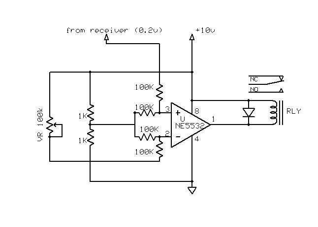
Hello , I would like to use a channel of a 2.4GHz receiver , to turn on a relay.
The output signal of the receiver varies from 0.15v to 0.26v , depended on the position of the transmitter's knob.

Can I use a simple transistor to activate the relay when the signal hits 0.29v ?

Thank you
 

I guess it gets complicated with opamp. Can I use it with single voltage or it needs +- power supply?
Any ideas about the gain that I need ?
I have 5- ne5532 lying around
 

datasheet :- https://www.ti.com/lit/ds/symlink/ne5532.pdf It will work on a 0, +10V or more PSU. You split the PSU to give you a false 1/2 Voltage point ( 2 X 1K resistor). Now you feed this voltage into both the+ and - inputs via a 100K resistor to each. Now the opamp thinks its running on a +- supply. You feed the - input via a 100K from a .2V reference source (pot across the Vcc line). You feed your receiver into the + input via another 100k . Connect a low current relay between the Vcc and the amps output, with a diode across the coil (cathode to +Vcc).
Frank
 
For anything that might have, shall we say, negative
consequences to false firing you would want a higher
standard for actuation. Otherwise some other joker's
Bluetooth gizmo might leave you minus a hand.

Nobody uses CW detectors for anything safety critical.

But of course this is a simple and benign science project.
Right?
 

A friend bought a cheap rc boat. Rc doesn't work. I have a nice 6ch kit so will try to use it.
His boat got 2 motors so I just want to control each motor at 100% as I don't want to deal with speed controllers and stuff .....

I would like some reliability or the receiver wich costs as 3 boats will swim to Turkey
 

datasheet :- https://www.ti.com/lit/ds/symlink/ne5532.pdf It will work on a 0, +10V or more PSU. You split the PSU to give you a false 1/2 Voltage point ( 2 X 1K resistor). Now you feed this voltage into both the+ and - inputs via a 100K resistor to each. Now the opamp thinks its running on a +- supply. You feed the - input via a 100K from a .2V reference source (pot across the Vcc line). You feed your receiver into the + input via another 100k . Connect a low current relay between the Vcc and the amps output, with a diode across the coil (cathode to +Vcc).
Frank
thats what I understood, is it correct ?


++ I have a ULN2804. Can I use that Instead of the whole previous ?
 
Last edited:

Status
Not open for further replies.

Part and Inventory Search

Welcome to EDABoard.com

Sponsor

Back
Top