Chamrog
Newbie level 2
Greetings,
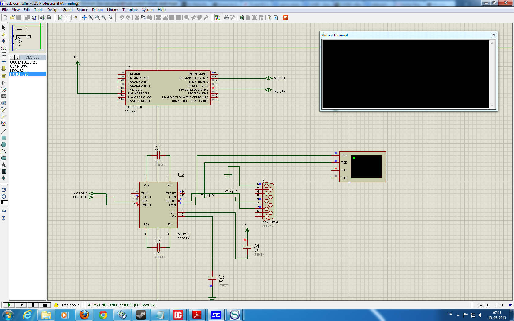
I'm using trying to set up communication using USART on the PIC1320, but it does not want to play nice") I do suspect that this is a configuration problem. I planned on being able to both send and receive, but so far nothing shows up, from the micro-controller. Im using proteus as simulator, and MikroC as the compiler.
I do suspect that this is a configuration problem. I planned on being able to both send and receive, but so far nothing shows up, from the micro-controller. Im using proteus as simulator, and MikroC as the compiler.
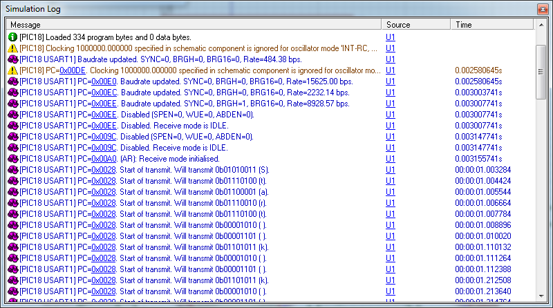
What i see.
1. nothing is output from the micro controller, i can however see that the usart does what i want
2. using the virtual oscilloscope i can see that the the things i type in the terminal are send "on the line"
3. i have set up RB0 to flash, and i can see that it does that as expected.
4. The RX line is high, but the TX line is constantly low, should it not be high when nothing is being send?
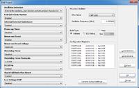
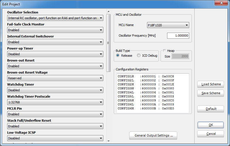
Part of the microcontroller config
Is there someone here that can tell me what silly mistake i have made?
/C
Mikroc Code, mostly just the example from MikroC with the on/off added as a sanity check.
I'm using trying to set up communication using USART on the PIC1320, but it does not want to play nice
I do suspect that this is a configuration problem. I planned on being able to both send and receive, but so far nothing shows up, from the micro-controller. Im using proteus as simulator, and MikroC as the compiler.What i see.
1. nothing is output from the micro controller, i can however see that the usart does what i want
2. using the virtual oscilloscope i can see that the the things i type in the terminal are send "on the line"
3. i have set up RB0 to flash, and i can see that it does that as expected.
4. The RX line is high, but the TX line is constantly low, should it not be high when nothing is being send?
Part of the microcontroller config
Is there someone here that can tell me what silly mistake i have made?
/C
Mikroc Code, mostly just the example from MikroC with the on/off added as a sanity check.
Code:
char i, error, byte_read;
           char uart_rd;

void main(){

  OSCCON = 0b01000000       ;     // set 1 MHZ
  ADCON0.B0 = 0;                // analog converter disabled
  ADCON1  = 0b11111111;                             // Configure AN pins as digital I/O
   TRISB.B0 = 0;
   UART1_Init(9600);               // Initialize UART module at 9600 bps
  Delay_ms(1000);                  // Wait for UART module to stabilize
  UART1_Write_Text("Start");
  UART1_Write(10);
  UART1_Write(13);

  while(1){
    LATB.B0= ~LATB.B0;
    delay_ms(100);
    UART1_Write_Text("k");
  UART1_Write(10);
  UART1_Write(13);
   }
  }