Continue to Site

Welcome to EDAboard.com

Welcome to our site! EDAboard.com is an international Electronics Discussion Forum focused on EDA software, circuits, schematics, books, theory, papers, asic, pld, 8051, DSP, Network, RF, Analog Design, PCB, Service Manuals... and a whole lot more! To participate you need to register. Registration is free. Click here to register now.

4013bt is very sensitive !!!

Status
Not open for further replies.

Sharagim

Advanced Member level 4
Joined
Feb 6, 2011
Messages
112
Helped
0
Reputation
0
Reaction score
0
Trophy points
1,296
Activity points
2,058
Hi,
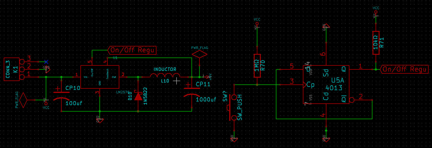
I want to use 4013bt for turn on and off a circuit (as you see in my schematic attached)
It is working ok but I see it is very sensitive . for example when I touch bt4013 by hand it make it on/off. Is it ok ?
Is there any way to make it be less sensitive ?

BR,
4013.png
 
Last edited:

A 4013 is a CMOS logic circuit, therefore its input is "very sensitive". To make it operate reliably, use pull-up resistors from input to +Vcc.
 

All unused inputs in a CMOS circuits should terminated either to ground or to V+. Otherwise you will likely get erratic results.

There is no attached schematic.
 

The 4013 has some Set and Reset terminals that must be properly terminated for it to operate reliably.
If I remember properly, the should be tied to ground, but please check the datasheet.
 

Sorry I missed the attachment , now it is in first post.
 

yes,cmos logic chip has high input impedance,so unused pins should configure as a constant level,such as pull-up or pull-down by 100K.
 
If timing is not very critical then consider to add a small shunt capacitor at input for de-bouncing purpose.
 
Thanks for your replies.
I solved the problem by a 1uf capacitor , Now it is working very stable.
Now I see another problem .
I am using this circuit for control of lm2576 (on/off) for making whole circuit on or off. This circuit working on battery too and when it is in standby mode for example in one day it used about 10% of battery (two li-ion 2Amp). I think it is a high!?
Do you think is there any solution to prevent this ?
 

The circuit consumed 200 mAHr in 24 hrs? Or about 8.3 mA of a continuous draw?

The LM2576 indicates a WORST CASE standby current of 0.2 mA...so you clearly have a load somewhere draining the excess current.

But we can only guess....
Therefore, to properly assist you, a complete schematic with component values is required.


Edit: For instance, the 10k pullup on the output of the 4013 is not required. The 4013's output is a totem pole, not an open drain.
You could have other issues like this.
 

Thx for reply.
Schematic attached.
I removed that 10k but nothing special happened yet (maybe I need more time to have a good estimation!).
 

Hmmmmmmmm, That is weird.

Do you have access to a multimeter?
Such that you can measure the supply current while in the "off" state?
 

I check it with multimeter.
I see 168mA when it is on and 15mA when it is in off stat!
 

Without being there to help you personally, you will have to check a couple of things;

1) That the LM2576 is turning off fully.

2) That there are no other components or connection in addition to what you are showing in your schematic.

3) That the flip-flop is not oscillating.
 
Thanks for reply.
After rechecking your comments I found out the problem.
I have a circuit for checking the input voltage with a voltage divider .
Input is about 8 v and I used a 4.7K and 1K to make it readable by ADC.
For instance I think changing the values to something like M will help (i am not sure yet) !!!
it is my pleasure to have your comment on this.

- - - Updated - - -

Now I see another problem when increase the value.
I see the output voltage of divider when is connected to ADC port is something different wrong for example unconnected show 1.3v but when I connect it to port I see 2.9v
 

I ignore which microcontroller you are using, but generally it is a good idea that the Thevenin equivalent of your resistor divider to be equal or less than 10k.
Higher values may cause errors.

For an 8V input, a voltage divider consisting of a pair of 20k would provide 4 volts and satisfy the requirement.

Having said that.... 4.7k and 1k across 8 Volt DO NOT consume 18 mA. You still have got SOMETHING ELSE connected.


Edit: "I see the output voltage of divider when is connected to ADC port is something different wrong for example unconnected show 1.3v but when I connect it to port I see 2.9v"
Are you sure the port is configured as an analog port and not something else?
 
Last edited:
Without being there to help you personally, you will have to check a couple of things;

3) That the flip-flop is not oscillating.

There are two flip-flops in a 4013 package. Do you have the unsed inputs for the other half tied to GND or Vcc?
You don't need a pull-up on the output.
 

I am using Xmega and you are right something was wrong here , unfortunately I forget to disable JTAG so that pin was working wrong.
After I did it now I see current in offline mode is going to something like half.
I think this 7-8 mA is for 4013 (not sure)
bking: I removed that resistor by an advise before and unused pins are connected to GND.
 

Status
Not open for further replies.

Similar threads

Part and Inventory Search

Welcome to EDABoard.com

Sponsor

Back
Top