Continue to Site

Welcome to EDAboard.com

Welcome to our site! EDAboard.com is an international Electronics Discussion Forum focused on EDA software, circuits, schematics, books, theory, papers, asic, pld, 8051, DSP, Network, RF, Analog Design, PCB, Service Manuals... and a whole lot more! To participate you need to register. Registration is free. Click here to register now.

12V to 5V regulator without wasting energy.

Status
Not open for further replies.

cartman007

Member level 2
Joined
Nov 13, 2012
Messages
45
Helped
0
Reputation
0
Reaction score
0
Trophy points
1,286
Activity points
1,638
Hey Guys.

I want to build a little device that I will insert into my car and therefore I need a power supply that will convert the 12V from my car battery to 5V.
But this device will be on constantly.
Now the device im going to power goes on 5V at 700mA MAX!
So my questions are.

1.How long will it take a car battery to go flat if a constant 3.5Watt gets sapped?
2.What kind of power supply do I have to build if I dont want to waste 7V into heat?

I know a regulator gives of the 7V of heat by dissipating (Turning it into heat)!
I dont want to waste energy like that since its going to run constantly.So will a switchmode power supply be the one to go for?
Since it will be 12V switced on and off to such a frequency that it will only be 5V, wont that be the best way to go?
Or is my understanding of switchmodes PSUs wrong.

If I cant use a Switch mode I would like to build one.Could anyone gives me any good ICs for switchmodes that will do the trick for 12V to 5v?

Thanks :)
 

3,5W @12V system is around 300mA (depends from voltage 12V nominal, 12,73V battery is full, 13,8V-14V engine running).

If we take for example 55Ah battery then 55Ah/0,3A = 183h for complete discharge (without chance to start engine).

Use switcher psu to avoid heat and waste of power. MC34063 with external MOSfet,....

TEXAS INSTRUMENTS LM2575HVT-5.0/NOPB 5V 1A
http://www.tme.eu/en/details/lm2575...circuits/texas-instruments/lm2575hvt-50nopb/#

LM2575EP-circuits.jpg
 

What is your efficiency target?

The circuit provided by TPETAR is a major improvement over a linear regulator. Efficiency can be further improved with a synchronous converter, but it costs more and is more complex.
 

One thing to consider: the car battery is not designed for complete discharge. If you do that more than few times (5-10), you can throw it away. The car battery can be discharged down to 70-80% maximum for normal operation, then it must be charged again. It is designed give huge ammount of power in short time, to start the engine, not for deep cycle operations.
 

1.How long will it take a car battery to go flat if a constant 3.5Watt gets sapped?

A dome light draws about an ampere. At 12V that is 12 W.

If your battery is in good shape, you can leave a dome light on overnight and the car will start.

However if the battery is old, or you leave the light on for 2 days, the battery may be unable to start the car.

--------------

Or, there is a chance the buck converter will draw only standby current with no load. A very small amount.
 

One thing to consider: the car battery is not designed for complete discharge. If you do that more than few times (5-10), you can throw it away. The car battery can be discharged down to 70-80% maximum for normal operation, then it must be charged again. It is designed give huge ammount of power in short time, to start the engine, not for deep cycle operations.

Pisoiu is right 100%. Only one addition to this, newer car batteries tolerate according to specification data for example Bosch car batteries around 300 complete cycles (down to 11,99V), if you go to 10,5V on starter batteries, there is high possibility to kill battery, for deep cycle 10,5V is not problem, but you dont have for sure deep cycle battery in car.
 

A good quality USB car adapter will do exactly that: buck the 12V fairly efficiently to 5V or thereabout. They are made for 500mA but the good ones will probably do well @700mA. If you're not too familiar with electronics this might be an easier, more likely to work and probably cheaper solution ;)
 

Also quiescent current should be taken in consideration.

Cartman007 if I may to ask, what device you plant to power with this psu ?
 

Perhaps what you really want is something like a small 6V
sealed lead-acid battery, a LDO regulator (or switcher,
but bear with me) for your load and a charging circuit
that runs off IGN and does not allow discharge when key
is off.

At 6V to 5V, your efficiency is 86% and you don't have
to work at it, at all - just pick a LDO with a decent low
ground current.

The charging efficiency, you don't care about one bit
in this application.

A stack of 5 fat NiMH batteries, such as could be
reclaimed from cordless power tools, is an alternative.
Not as many A-h as a SLA battery, but then, junk
cordless tools are in the trash bins all the time and
usually only one or two of the cells are really bad.

Of course if this needed to be super compact, that's
a mark against the 6V battery idea; but it sounds
like a semi-permanent install to me, and there is always
some unused cavity in a car.
 

My idea is to run a raspberry Pi of the 12V battery of the car.
+ I could think of allot of different tasks I could use 5V for in my car.
Perhaps hack a USB hub so source power for all kinds of USB chargeable devices.

will 144 hours of 3.5watt drive a car battery below 70% ?
 

If you dont plan to start engine often, consider usage of small solar panel 15-20W, to recharge car battery.
 

If you dont plan to start engine often, consider usage of small solar panel 15-20W, to recharge car battery.

But 3.5Watt drain it for atleast 5 days would it? Although ive read that a car battery should stay above 70% charge.
 

Yes, car battery is float battery, gives higher currents for short time (starting) but its not designed for complete cycling. This type of battery have long life if you use or cycle max up to 30% of battery capacity.

3,5W @12 on 55Ah is around 183h. For 183h 3,5W complete discharge new and fresh fully charged battery. For 30% this time is much much lower.

If car have alarm or other devices which drain current when engine is off, and engine is not often started, consider usage of mentioned solution or recharge battery on some other way.

If possible lead acid should be always at full level, do not keep battery at 70% for long time, sulphatisation process will occur on lead plates, and as product of that battery start to lose capacity and give smaller currents (internal resistance increase).
 

But 3.5Watt drain it for atleast 5 days would it? Although ive read that a car battery should stay above 70% charge.

For comparison, measure current draw from your battery when everything is off. There will probably be a small amount, up to 30 or 40 mA (according to one spec).

This powers the clock. Maybe a computer. Maybe a receiver for your wireless lock/unlock signal?

12.5 V times .04 A, makes 1/2 W continual draw.
 

Ok soo ive taken the first steps.

Here is the IC I will be using AP1501-50

**broken link removed**

Now this will be my first Switchmode power supply design so bear with me.Correct me if I am wrong or your opinions will help.

I will most likely use the Adjustable Type Circuit like in the datasheet.
And if I use the formula given below the circuit I get R2 = 490Ohm IF i chose R1 = 1500Ohm and Vout = 5V which is ideally what I want?
But what should the caps be? What do they do anyway ?
I have seen switch mode power supply ICs in a really simplified schematic like really bare minimum needed for basic operation and still all I can see it do is filter noise?

THanks
 

Ok soo ive taken the first steps.

Here is the IC I will be using AP1501-50

**broken link removed**

Now this will be my first Switchmode power supply design so bear with me.Correct me if I am wrong or your opinions will help.

I will most likely use the Adjustable Type Circuit like in the datasheet.
And if I use the formula given below the circuit I get R2 = 490Ohm IF i chose R1 = 1500Ohm and Vout = 5V which is ideally what I want?

The 1501-50 is fixed at 5V. It appears you can use the schematic '(1) Fixed type circuit' (even though the chip is marked AP1501-33, and the output says 3.3V).

Your output will be 5V. I think you will not need external resistors.

But what should the caps be? What do they do anyway ?
I have seen switch mode power supply ICs in a really simplified schematic like really bare minimum needed for basic operation and still all I can see it do is filter noise?

THanks

The output smoothing capacitor does the same job as in conventional power supplies. However if you operate at 150kHz, then it does not need to be so large. My simulation shows 10uF will yield 1% ripple.

With no capacitor, the converter could still do its job, except it would have to operate at a much higher frequency.
In that case the coil would be acting more as a choke on the pulsed DC.

If you watch my Youtube video 'buck boost buckboost converters (Animated)', you'll see a simulation depicting when and where current flow takes place. It portrays flux fields building and collapsing, changing EMF, capacitors charging and discharging.

www.youtube.com/watch?v=FT_sLF5Etm4
 

Thanks allot Brad!

Really great video by the way!

With what do you simulate the circuit?
If you build the schematic in the simulating program do you litteraly use only the minimum of components?
Frequency generator, Transistor, Op amp, Coil and Caps?


Thanks allot for the effort!
 

My videos show simulations made by my own homebrew program. (Perhaps someday it will be good enough for public distribution.)

The pulse generator is 'invisible'. The algorithm designates a wire as having the supply voltage on one end for a certain number of frames, then 0V for a certain number of frames.

I have not yet modeled an op amp. That is just one of several hurdles I have to conquer in order to devise the ultimate electronic circuit simulator.

------------------------

Although Falstad's simulator has its limitations, it can do a number of things better than mine.

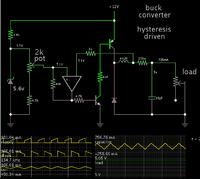
Here is a buck converter to your specs...
driven by hysteresis by means of an op amp, with voltage regulation.


You can see it in action by clicking the link below. It will open the website www.falstad.com/circuit, load my schematic, and run it on your computer.

https://tinyurl.com/conpe7m

This is just a barebones simulation. It not necessarily the most suitable design for your purposes, since it lacks features which are built into a commercially manufactured IC.
 

Thanks allot Brad!

Ok so im going to go buy all the components just couple more things.

Im literally going to design my board like the circuit I see in the data sheet...Just without the white spaces of course.

I was wondering if there is any special components like special caps and inductors that work better with Switchmode PSUs then other?

For instance. Instead of a Ceramic cap I ll take an Aluminium for the 10uF noise filter on both the Cin and Cout etc etc.

Thanks


Read documents in attachment.
 

Attachments

  • en528035.pdf
    108.4 KB · Views: 252
  • Selecting capacitors for SMPS Filtering.pdf
    351.3 KB · Views: 152

Status
Not open for further replies.

Similar threads

Part and Inventory Search

Welcome to EDABoard.com

Sponsor

Back
Top