Continue to Site
Follow along with the video below to see how to install our site as a web app on your home screen.
Note: This feature may not be available in some browsers.
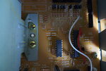
locate drawing C-2 coord. +12V, Gnd,-26V and lowV ac on P4.
There's some bad news: I think this is not possible because the original power supply is quite complex, it gives multiple AC and DC voltages.
The solution is the repairing if the transformer is good yet. It would not so hard because only the other items be tested and replaced.
If no current is drawn, there may be no need to move it. Locate the row and column address outside the schematic and see location C-1 for the location of DC connections and ac signals.
....The machine is brand new and unused....
The purpose of replacing the standard transformer with a high quality linear external psu is to move the 50Hz magnetic field away from the playback head and electronics.
Well, that is a different situation! What I would do (if you cannot reduce the magnetic disturbances (to the minimum as you want) with newly inbuilt permalloy shielding plates):
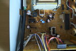
- Should be removed the whole transformer and an appropriate length wires should be connected to all pins.
- If this is not possible or problematic, should be removed the whole PSU PCB (CONT M PCB 2/2).
It has two sockets (P4 and P12) and five hard-wired cables (1 to 5 numbered) to the "PCB CONT M 1/2" (if I interpret the diagram). They should be extended accordingly.
Otherwise we do not really understand the diagram: the two 'F' transformer terminal (15 and 17), both are going to the same point (1) on the PCB 1/2. Short circuit or a diagram error?
It can be seen that a simple external DC power supply is not a solution ...
Janaaoi. Your post #1 with attached schematic has spreadsheet like numbers and letters on outline to help locate intersection on a page. C-1 is between U.S.A. and Canada on left side which shows the common exit DC voltage pins for the external power supply, which is what you asked for.
Now I'd like to ask, where do you find a brand new $6k tape recorder with no external power supply and no after sales support? ( or did someone find it and ran a 120V unit off 240Vac?
Measure voltage at D21, D23, D25 ( right side of diode on schema. ) and inject 3 external psu voltages using diodes at slightly higher voltage so as to supply all the current. Ensure anode is same direction in each case (depends on V polarity).
With no significant AC current there should be no significant hum
1. D20 and D21 are wired OR full wave Ac rectifier diodes, therefore common cathode point so D20 is irrelevant, however the AC is fed to the same connector for some other timing purpose so that is still be required.1. Are these the only three relevant diode bypass points, what about D20?
2. As I will be using a quality low ripple linear PSU, won't the feeds at these points be put unecessarily through two sets of similar components?
3. How would I physically attach the different voltage rails to such small diodes?
4. How would I introduce the negative polarity VDC at D25?
5. What about the PSU ground feed - I don't know where that would be attached to common ground?
A few further questions:
1. Is there anything I can damage by attempting this set up? Bearing in mind this is a new deck that I cannot afford to spoil. For example, if I use crocodile clips to try it, and one comes off, will that loss of voltage upset anything else permanently?
2. Can you explain what you mean by positive floating external Vdc? The psu will be earthed to a common ground on the board. How is it "floating"?
3. And why have you quoted 24V when I found 28.78 (29)V?