Continue to Site

Welcome to EDAboard.com

Welcome to our site! EDAboard.com is an international Electronics Discussion Forum focused on EDA software, circuits, schematics, books, theory, papers, asic, pld, 8051, DSP, Network, RF, Analog Design, PCB, Service Manuals... and a whole lot more! To participate you need to register. Registration is free. Click here to register now.

Modulating Ic on a BJT?

Status
Not open for further replies.

juansg

Newbie level 3
Joined
May 4, 2013
Messages
3
Helped
0
Reputation
0
Reaction score
0
Trophy points
1,281
Activity points
1,310
Hi,

I am working in a project with a circuit that a college gave me, but he is not with me anymore, so I am trying to figure this out with no luck.

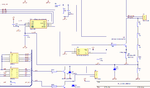
The idea is to be able to modulate the current in Ic, using the voltage source (ultimately, the Vs will actually be the pwm output of a microcontroller). I am simulating this circuit, but it's not working as I was told it should work. Anybody has any insight on how to fix it?

thanks

simple-iv-tracer.png
 

It should work OK. It's basically a controlled current sink with the voltage dropped across R2 being compared to the voltage at the '+' input of the op-amp. I have doubts about a TL082 being able to provide sufficient output current though. The voltage at the '+' input is the PWM averaged by R3/R4 and C2. You should feed it with a signal going from ground voltage to more than (load current * 10mOhms) volts.

Brian.
 

Some parameters don't fit at all, causing failure of the overall circuit. You e.g. have a 100 A current source in the photovoltaic element model but an output resistance that doesn't allow more than mA. The BJT might sink 1 or 2 A according to base current limitation, etc.

Instead of making us guess about reasonable parameters, you should better tell the basic specifications and the intended purpose of this circuit.
 
  • Like
Reactions: LvW

    LvW

    Points: 2
    Helpful Answer Positive Rating
I'm guessing the photovoltaic module is just a theoretical device to satisfy the simulator. Given the values in it, that poor 1N4148 isn't going to last long !

Brian.
 

I'm guessing the photovoltaic module is just a theoretical device to satisfy the simulator.
Yes, that's my assumption, too. But it doesn't even work in theory because the parameters are cobbled together without thinking or faulty copied.
 

thanks for the replies. The current source + resistors on the right side was just a poor attempt to model the photovoltaic module. It's a 285W module, with the I-V curve that I've attached. The idea is to be able to use a PWM ramp at the Op Amp's Vin and being able to regulate a current flow from 0A to about 8A.

The original circuit was actually working, and I was given a hand written version of it. I just got access to the full circuit (see it attached), but I don't get how's that possible.

The main problem I see is that using such a tiny load resistor, the voltage and current at the base of the BJT go crazy high. Any comments are more than welcomed.

- - - Updated - - -

Please, note that the wire connected to the emisor and going upwards in the diagram, just goes to a current sensor and then to ground. Also, somebody made a mistake drawing the 500uOhm resistor, it's actually a 0.01Ohm resistor in the circuit
 

Attachments

  • iv.png
    iv.png
    33.4 KB · Views: 70
  • Full.png
    Full.png
    69 KB · Views: 66

O.K., the photovoltaic element model should be replaced by something meaningful. In case of doubt, you might use a behavioral model, utilizing respective features of your simulator. A silicon diodes based equivalent circuit would use a number of diodes according to the photolement design, e.g. 50.

The BJT current source can work with a darlington transistor. A current sense resistor of 10 mOhm is already low, 0.5 mOhm is just out of it.
 

The BJT current source can work with a darlington transistor. A current sense resistor of 10 mOhm is already low, 0.5 mOhm is just out of it.

I agree. Somebody made a mistake drawing the 500uOhm resistor, it's actually a 0.01Ohm resistor in the circuit. If I'm having these problems simulating the circuit with 0.01ohm, I wouldn't like to try with 0.5mOhm.
 

your main problem is that you have a constant current source of 100A feeding a diode, so the volt drop across the diode is 1V at a max or the diode is toast. This volt drop is not enough to put Q1 into a good operating area, try 2->3V drop across a couple of diodes. In the original circuit the feed was from solar cells 12-> 70 V?
Frank
 

Status
Not open for further replies.

Similar threads

Part and Inventory Search

Welcome to EDABoard.com

Sponsor

Back
Top