Continue to Site

Welcome to EDAboard.com

Welcome to our site! EDAboard.com is an international Electronics Discussion Forum focused on EDA software, circuits, schematics, books, theory, papers, asic, pld, 8051, DSP, Network, RF, Analog Design, PCB, Service Manuals... and a whole lot more! To participate you need to register. Registration is free. Click here to register now.

Bandgap temperature sensor

Status
Not open for further replies.

kokabanga

Member level 5
Joined
May 2, 2005
Messages
88
Helped
12
Reputation
24
Reaction score
9
Trophy points
1,288
Activity points
1,863
Hi all,

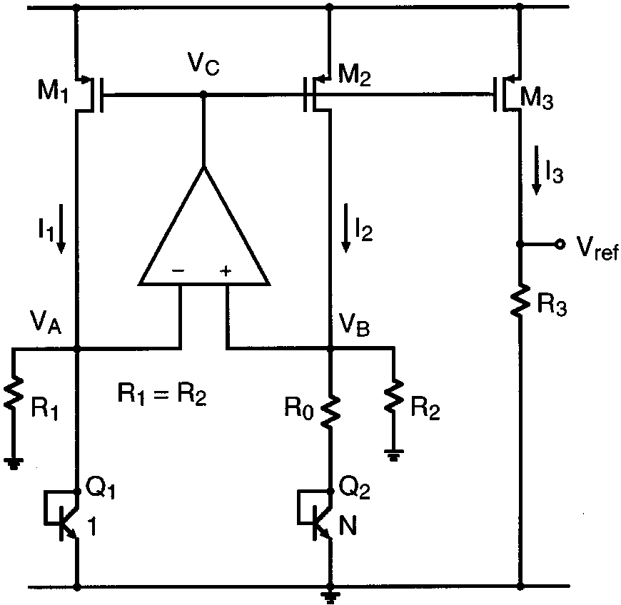
I need to implement a temperature sensor based on the circuit shown in the attached schematic. Unfortunately, the current flowing thru M1/M2 is not PTAT. So then how can I implement a temperature sensor based on this architecture? Any guidance will be helpful.

Thanks.


Hi,
Two transistors Q1 and Q2 with current sources are generate PTAT voltage Vbe1 - Vbe2 = Vt*ln(N).
I think that for this task you need to delete feedback and resistors, and get PTAT voltage VA - VB (you must setup dc point of current sources of M1 and M2 of cource).
 

So then how can I implement a temperature sensor based on this architecture? Any guidance will be helpful.
By simply omitting R1 and R2, reducing the band gap circuit to a basic PTAT generator. See Razavi Figure 11.19 versus 11.39
 

It is not possible to remove R1, R2 as they are involved in generating the PTAT part of the bandgap output voltage as seen in the equation below.
Untitled.jpg
 

It is not possible to remove R1, R2 as they are involved in generating the PTAT part of the bandgap output voltage as seen in the equation below.
logic behind this statement? Where did you get the equation now?

I presume other forum members can read Razavi and check the derivation in paragraph 11.4 PTAT current generation
 

It is not possible to remove R1, R2 as they are involved in generating the PTAT part of the bandgap output voltage as seen in the equation below.
View attachment 90896
I think that is formula for output voltage of bandgap, which is independent from temperature and it got from assumption that Va = Vb.
And you may generate PTAT current only with two transistor (Q and nQ) and current sources.
 
Last edited:

"It is not possible to remove R1, R2 as they are involved in generating the PTAT part of the bandgap output voltage as seen in the equation below."

As seen in your equation, the PTAT portion (R3*ln(N)*Vt/R0) has no terms of R1 or R2. As FvM suggested, simply remove those resistors and you'll get a PTAT voltage.
 

Status
Not open for further replies.

Part and Inventory Search

Welcome to EDABoard.com

Sponsor

Back
Top