Continue to Site

Welcome to EDAboard.com

Welcome to our site! EDAboard.com is an international Electronics Discussion Forum focused on EDA software, circuits, schematics, books, theory, papers, asic, pld, 8051, DSP, Network, RF, Analog Design, PCB, Service Manuals... and a whole lot more! To participate you need to register. Registration is free. Click here to register now.

Boost Converter Serious Problem

Status
Not open for further replies.

Sherif8

Newbie level 5
Joined
May 3, 2012
Messages
8
Helped
0
Reputation
0
Reaction score
0
Trophy points
1,281
Activity points
1,361
Hello everybody!

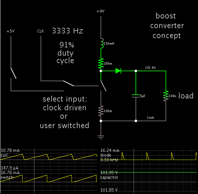
I'm trying to design a boost power supply stepping up from 9v to 105v

**broken link removed**

The first stage is simply a level shifter. I tried to apply the equations in TI application note here **broken link removed** but it didn't work. The change of the pulse width doesn't matter at all with the value of the final output which settles on the VDSsat of the IRF no matter what the values of the coil and the capacitor are! This doesn't sound any logic at all!!

Any help please?

Note: I posted a thread before regarding this issue and i got a solution regarding the specs back then, the specs now changed and i thought a new thread would be more practical.
 

The problem is your level shifter is too slow and thus with gate capacitance during switching and open collector rise time, it will not work as a fast switch with di/dt.

recommendation . use an active pullup switch for driver such as CMOS buffered driver running off 9V to shift level from 3 to 9 input to CMOS use a better level shifter design with fast off to ON transition time < 1uS.
 
Did you check for the correct waveform at the Drain of Q3 ? The simulation may not be working correctly to switch Q3 on/off.

- - - Updated - - -

Sorry the very good answer of SunnySkyguy went thru while I was typing mine.
 

What results do you get? "but it didn't work. " means??

What is ESR of L3? What is ESR of C3? What is on resistance or ESR of diode, D3?


Th IRF930C has Rds On (max) 0.4Ohm , 5.4A,10Vg
 

I think the Resistor R12 is the ESR of L3
 

Make sure 9V is low impedance too. with no ripple.

a quick lookup of impedance of LC shows resonant frequency impedance 150~ 200 Ohm @ 150~200Hz so pulse at 180uS or 5.5KHz

quick check using basics

from schematic
mosfet IRF930C has Rds On (max) 0.4Ohm
max series resistance incl. Rs= 0.4 + 0.2R = 0.6R

Max current = Vdd9/Rs = 9V/0.6R = 1.3A ( if left ON)

find Actual peak current..

inductor time constant , T=L/Rs = 150uH /.6R = 250us ,

Pulse tON= 80us tOFF= 100us, thus 80/250us thus ~ 30% of Imax = .3x1.3A ~ 0.4A

V= L dI/dt for L=150uH, dI = 0.4A , V=100V
dt=L dI/V = 150uH * 0.4 /100 = 0.6us

This assumes no resonant diode Cap load.

This means your turn OFF time of the MOSFET must be < 0.75us from 0.5A to 0 to generate 100V. Does it?

You can increase the voltage by increasing the current by lowering the clock frequency or reducing the inductor value.

AS Brad says 200Hz.... which is the resonant frequency of LC filter....

I suggest you ask AD why their formula does not work.
 
Last edited:

Your pulse rate values (80 and 100 usec) calculate to 5555 Hz.

However if your coil is really 150 mH, then it needs a slower switching frequency. More like 200 Hz. You may need to use a longer duty cycle ('On' time) as well.
 

Without seeing all your work and choice of passive parts, it is hard to see where you went wrong.

Perhaps the choice of ripple current to max load current? You never specified either.
perhaps the choice of clock rate? In any case, low output voltage can be caused by poor diode (ESR) choice, slow level shifter, too much load, too fast clock rate, thus too low current resulting in too high inductor value.
 

The problem is your level shifter is too slow and thus with gate capacitance during switching and open collector rise time, it will not work as a fast switch with di/dt.

recommendation . use an active pullup switch for driver such as CMOS buffered driver running off 9V to shift level from 3 to 9 input to CMOS use a better level shifter design with fast off to ON transition time < 1uS.
I don't think it's s a problem of the level shifter because i've already checked the output pulse and it's almost the exact inversion.

Did you check for the correct waveform at the Drain of Q3 ? The simulation may not be working correctly to switch Q3 on/off.

- - - Updated - - -

Sorry the very good answer of SunnySkyguy went thru while I was typing mine.
Yes i did, and it's good

What results do you get? "but it didn't work. " means??

What is ESR of L3? What is ESR of C3? What is on resistance or ESR of diode, D3?


Th IRF930C has Rds On (max) 0.4Ohm , 5.4A,10Vg
Meaning that the pulse width change doesn't affect the output, it settles on the VDSsat whatever what.
The comment below said it correct, R12 is the ESR of the coil. However, i was working with 1N4148 when the specs were to out 100v, now that i need 105v i used a general purpose *without simulation profile* diode to achieve the required voltage then back to choose the right one.

I think the Resistor R12 is the ESR of L3
Correct!

Your pulse rate values (80 and 100 usec) calculate to 5555 Hz.

However if your coil is really 150 mH, then it needs a slower switching frequency. More like 200 Hz. You may need to use a longer duty cycle ('On' time) as well.
No that was rubbish, i was trying something else, the correct values should be 300usec as Period, 20usec as Pulse width, the pw however is a part of issue.

Make sure 9V is low impedance too. with no ripple.

a quick lookup of impedance of LC shows resonant frequency impedance 150~ 200 Ohm @ 150~200Hz so pulse at 180uS or 5.5KHz

quick check using basics

from schematic
mosfet IRF930C has Rds On (max) 0.4Ohm
max series resistance incl. Rs= 0.4 + 0.2R = 0.6R

Max current = Vdd9/Rs = 9V/0.6R = 1.3A ( if left ON)

find Actual peak current..

inductor time constant , T=L/Rs = 150uH /.6R = 250us ,

Pulse tON= 80us tOFF= 100us, thus 80/250us thus ~ 30% of Imax = .3x1.3A ~ 0.4A

V= L dI/dt for L=150uH, dI = 0.4A , V=100V
dt=L dI/V = 150uH * 0.4 /100 = 0.6us

This assumes no resonant diode Cap load.

This means your turn OFF time of the MOSFET must be < 0.75us from 0.5A to 0 to generate 100V. Does it?

You can increase the voltage by increasing the current by lowering the clock frequency or reducing the inductor value.

AS Brad says 200Hz.... which is the resonant frequency of LC filter....

I suggest you ask AD why their formula does not work.
I'm going to try that... Thanks
 
Last edited:

I made a simulation. 3333 Hz. Coil 180mH.

It can work. The duty cycle needs to be 91%.


I made the load 100k ohms.

Your schematic shows no load. With no load, the charge on the capacitor can build to levels of several hundred volts. This would fry the switching device (mosfet), unless it is rated for high voltage. Is there a chance it is fried?
 

Status
Not open for further replies.

Similar threads

Part and Inventory Search

Welcome to EDABoard.com

Sponsor

Back
Top