Continue to Site

Welcome to EDAboard.com

Welcome to our site! EDAboard.com is an international Electronics Discussion Forum focused on EDA software, circuits, schematics, books, theory, papers, asic, pld, 8051, DSP, Network, RF, Analog Design, PCB, Service Manuals... and a whole lot more! To participate you need to register. Registration is free. Click here to register now.

Microcontrollers and motors

Status
Not open for further replies.

Ahmed.Soliman

Junior Member level 1
Joined
Oct 22, 2010
Messages
19
Helped
0
Reputation
0
Reaction score
0
Trophy points
1,281
Activity points
1,434
Hello guys ,
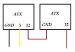
I have a problem that I have to control some motors using micro-controller ... Each motor can draw up to 12 Amps .. and I have 2 ATX power supplies connected in series to get 24 V for the motors and 5 V for the microcontroller .... I've tested the circuit and the firmware without connecting the motors and it works great .. but when I connect a motor , the circuit behaves weirdly when I start any motor !
Is there any hardware that I should add to solve this problem ?

BTW the current drawn by the motor now is 5 Amps only .

Thanks in advance
 

Noise, EMI (Electro Magnetic Interference) etc are all the causes for this.

When the motor starts, the noise generated in the power lines resets the microcontroller which is easily prone to such noise, and will start behaving abnormally.

You need strict isolation for the microcontroller from all such external interferences.

When you say controlling the motors, how exactly do you mean? Through relays? Put the circuit for analysis.
 

All voltage and current sensing should be isolated and also try to cover your microcontroller pcb with a copper sheet, that worked for me in an application.
 

I have 3 motors ,, I'm using relays to control the direction of 2 motors ,, and relays + Mosfets to control the speed and Direction of 1 motor ..
I think that " When the motor starts, the noise generated in the power lines resets the microcontroller which is easily prone to such noise, and will start behaving abnormally. " Perfectly describes my case ,, so how can I isolate the micro-controller ?
I'm not using any voltage or current sensing .. And I'm supposed to use a single DC power supply 48V 40A at the end of the project ?
Kindly find the attachment
 

Attachments

  • EXPORT.PDF
    80.6 KB · Views: 103

The power Supply Part is not shown in the attached circuit. Particularly the power supply for the microcontroller. How is the +5V derived?
Try providing a separate supply for microcontroller, instead of deriving it from the same ATX power supplies that you are using for Motor.

And I also do not see the flywheel diode across the Relay coils. Are they there?
 

I'm driving the Relays from ULN2003 ,, It has a built in free wheeling diode ...
I have no problem when powering the Micro-controller from another supply ( I had used the 5 Volts form the PICKit 3 ) ,, the problem is that I can't do this in the final project .. It's required that I must use only 1 DC supply which is as I said 48 V and 40 A ...
I'm not responsible for the power supply design so I don't have the schematics now .
 

Attachments

  • Capture.JPG
    Capture.JPG
    22.8 KB · Views: 82

I'm driving the Relays from ULN2003 ,, It has a built in free wheeling diode ...
I have no problem when powering the Micro-controller from another supply ( I had used the 5 Volts form the PICKit 3 ) ,, the problem is that I can't do this in the final project .. It's required that I must use only 1 DC supply which is as I said 48 V and 40 A ...
I'm not responsible for the power supply design so I don't have the schematics now .


Make decent psu for your needs, usually scotch tape-glue design variants are bad in the long run.

Use iron trafo or make lighter variant as SMPS.

I dont see needs for PICKit 3 usage just for 5V supply. Maybe after this design exibition you might look for a new PICKit 3.

Good and reliable psu represent good base for project.
 
Could you recommend any decent power supply circuit ?
We thought of a SMPS ,, but failed to implement it :) I think that the real question is how to make a decent power supply :)
 

It seems obvious now that noise on your 5V supply to the MCU is causing the problem. So, perhaps you could just clean up that 5V supply with some filtering? Depending on how low that 5V is dropping, you may need a beefy cap. Do you have a scope you can probe the 5V line with? Note, that MCU can run with anything from 2-5.5V.
 
Driving of your mosfets is wrong. Gate voltage for "on" state is less than 5V. It is not enough for IRF540 and mosfet will not work correct. It don't make noise problems, but you first fix it. For noise, isolation by optocouplers is easiest way. Other methods need experience.
 
Last edited:
Though probably not related to your MCU issue, your FET gate drive circuit is a little sketchy as noted above.

Firstly, you should be trying to drive the IRF540N gates (Vgs) to 8-12V, not 18V (too close to the absolute max of 20V). Secondly, the way you have your BJTs hooked up is not going to behave the way you wanted. For example, when PWM goes high (5V), Q2 will indeed turn OFF but Q3 will start to turn on, and once the emitter reaches a voltage of 4.3V, it will start to turn off. So, the gates of the IRF540s will settle at ~4.3V. The Vgs(threshold) is 2-4V, so they will likely turn on, but it is not a recommended design.
 
Thank you dude :) I'll give the schematics to the power supply team :)

- - - Updated - - -

Daniel ... I think I'm driving the MOSFETs by 18 V :) and they don't heat up at all .. I've tried many driving methods and I got the best results with this one :) Please check the schematics again and explain why it's less than 5 V ? :) Thanks for your reply :)

- - - Updated - - -

I think that your post makes sense .. I'm using 18 V because I don't want to use any heatsink .. and I have 24VDC so I thought that 18 V won't dissipate much heat as the 12 V regulator of course .
BTW I'm using IRF3205 now .. so how can I fix this problem ? Should I use a Mosfet driver like IR2110 ? I don't have any SMD Components and I do care about the size :( ? Any suggestions ?
I Think that adding a stage of pulling up resistor and a NPN transistor to turn on and off My MOSFET Driver with a higher voltage than 4.3 V will help ,, Am I missing anything ?
 
Last edited:

Hi,

You driving circuit (totem pole bjt driver for mosfets) is made with two BJT's in common collector connection. Input signal for your driver is PWM signal from MCU 5V TTL range. For high state, Vin=5V, Vout=Vin-Vbe(Q3)=5-0.7v=4.3V. You can check it simple by multimeter. Just put 5V on input of your driver circuit and measure voltage on output your driver. You will get voltage about 4-4.4V. Check and tell us what you measured.

You can improve your driver circuit with bjt, but I suggest use driver chip. IR2110 is for bridge topologies, but you can use it.

Schematic:

https://http://2.bp.blogspot.com/-UEgnFQCdft8/UPvoCJqiTQI/AAAAAAAAAaQ/XX-5HJ6H85s/s1600/IR2110+-+5.png

Instead 12V, you can use your 18V and you can drive more than one mosfet. 5v get from your MCU supply. I suggest to use 15V instead 18V because 18v is too close Vgsmax.
 
Last edited:
Thanks Daniel ,, I've simulated the totem circuit and found that you are right :) ... I'll change the regulator to 7815 ... My problem is the size of IR2110 and IR2112
These are the only locally available MOSFET drivers here in Egypt , and I don't need the high side driving part ,, so It will be a waste for money and space If I used them in this project . I'll add a bjt to increase the 5V from the micro-controller to 15 V ... so the Vgs will be around 14.3 V .
BTW do you have any idea how to use this totem pole circuit for a P-Channel MOSFET ?
Thanks again :)
 

What if the Source of the P-Channel should be connected to 48 V supply ?
 

add filtering capacitor on both sides of the regulator , and electrolytic capacitors of say 1200uF ( and with Voltage twice that of your supply) on the motors power section , near the relays or mosfets . that is a garanteed solution

good luck
 

Status
Not open for further replies.

Similar threads

Part and Inventory Search

Welcome to EDABoard.com

Sponsor

Back
Top