Continue to Site

Welcome to EDAboard.com

Welcome to our site! EDAboard.com is an international Electronics Discussion Forum focused on EDA software, circuits, schematics, books, theory, papers, asic, pld, 8051, DSP, Network, RF, Analog Design, PCB, Service Manuals... and a whole lot more! To participate you need to register. Registration is free. Click here to register now.

Driving Mosfet problem

Status
Not open for further replies.

auto_mitch

Full Member level 3
Joined
Oct 14, 2004
Messages
172
Helped
16
Reputation
32
Reaction score
3
Trophy points
1,298
Activity points
1,240
Hi!
I am trying to build a high power speed controller for a DC motor.
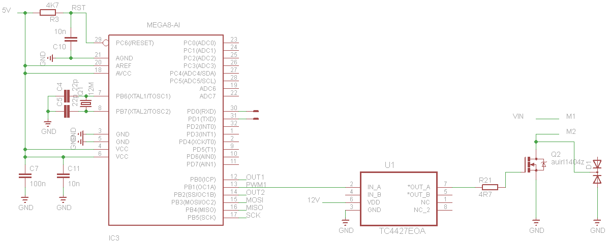
I want to control the motor only to one direction. I decide to use a single mosfet with a mosfet driver as the following schematic shows.
Mosfet:http://www.irf.com/product-info/datasheets/data/auirl1404z.pdf
Driver: **broken link removed**
Schematic


The frequency of the pwm is 23,53Khz. The problem that i face is that the mosfet is getting very hot when i try to change the duty cycle of the pwm. I have tried lower freq like 5Khz but the mosfet is getting hot again.
I dont know if there is something wrong with my driver. Any ideas?
 

I'd add a pulldown resitor beteween gate-gnd to prevent the gate charging to the threshold voltage and neginning to operate in the linear region during low period of PWM (the threshold voltage is very low only Vsink + 1.4v-2.7v on that FET) although the driver probably has this functionality inbuilt, adding a 1k resistor from gate to source wouldn't hurt. Also that MOSFET does have a fairly large gate capacitance - rise time will be failry high driving with only 1.5A. If you try something like 1% duty cycle or less, does the motor still move?
 

First, you need the frequency high enough that you cannot
ramp FET current past its ratings in the period at full (or, say,
90%) duty. That is all about motor inductance. And your FET
needs to be sized such that at full designed running current
you can take a full period's worth of ripple and still be OK.

The FET wants heat sinking of course because this is the
basis of current ratings, a certain maximum Tj.

If the FET gate is not stiffly driven then there will be a
lot of excess dissipation during the edges. It looks like
this is OK.

But the drain's "snubber" looks all wrong, there is no flyback
for the armature current other than either the FET, or the
diode in that 2-pack breaking down. Keep on doing that
and somebody's gonna get hurt.
 

Status
Not open for further replies.

Similar threads

Part and Inventory Search

Welcome to EDABoard.com

Sponsor

Back
Top